链路聚合 + MSTP+VRRP+OSPF 完整配置
·
一、实验背景与需求
企业网络要求业务不中断,需要解决链路单点故障、网关单点故障、二层环路、静态路由维护麻烦问题。 实验需求:
- 划分 VLAN,接口配置 Access/Trunk
- 配置链路聚合实现带宽叠加、链路冗余
- MSTP 多生成树,不同 VLAN 指定不同根桥,实现负载分担
- IP 地址规划
- VRRP 虚拟网关冗余备份
- OSPF 实现全网设备路由互通
二、拓扑与 IP 规划
拓扑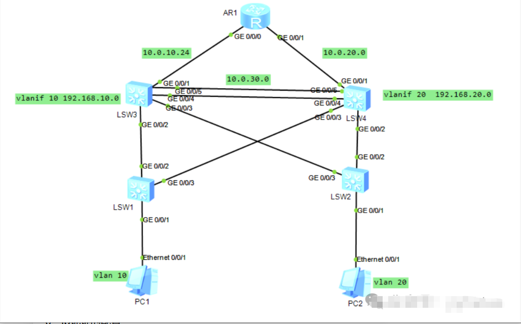
- 核心:LSW3、LSW4;接入:LSW1、LSW2;出口路由器 AR1
- PC1 属于 VLAN10:192.168.10.10/24,虚拟网关 192.168.10.254
- PC2 属于 VLAN20:192.168.20.10/24,虚拟网关 192.168.20.254
互联网段
表格
| 互联链路 | 网段 |
|---|---|
| AR1‑LSW3 | 10.0.10.0/24 |
| AR1‑LSW4 | 10.0.20.0/24 |
| LSW3‑LSW4 聚合 | 10.0.30.0/24 |
MSTP 规划
- Instance1 映射 VLAN10,LSW3 为主根桥,LSW4 备份
- Instance2 映射 VLAN20,LSW4 为主根桥,LSW3 备份
VRRP 规划
- VLAN10:LSW3 优先级 120(主),LSW4 优先级 100(备),虚拟 IP:192.168.10.254
- VLAN20:LSW4 优先级 120(主),LSW3 优先级 100(备),虚拟 IP:192.168.20.254
链路聚合:LSW3 与 LSW4 之间 GE0/0/4、GE0/0/5,模式 lacp‑static
三、完整配置脚本
LSW3 配置
system-view
sysname LSW3
vlan batch 10 20

#链路聚合Eth‑Trunk1
interface Eth‑Trunk 1
 mode lacp-static
 port link-type trunk
 port trunk allow-pass vlan 10 20
interface GigabitEthernet 0/0/4
 eth‑trunk 1
interface GigabitEthernet 0/0/5
 eth‑trunk 1

#对接AR1
interface GigabitEthernet 0/0/1
 port link-type trunk
 port trunk allow-pass vlan 10 20

#对接接入LSW1
interface GigabitEthernet 0/0/2
 port link-type trunk
 port trunk allow-pass vlan 10 20

#MSTP配置
stp mode mstp
stp region-configuration
 region-name MST‑TEST
 instance 1 vlan 10
 instance 2 vlan 20
 active
stp instance 1 root primary
stp instance 2 root secondary

#三层VLANIF接口
interface Vlanif 10
 ip address 192.168.10.1 255.255.255.0
interface Vlanif 20
 ip address 192.168.20.1 255.255.255.0
interface Vlanif 1
 ip address 10.0.10.2 255.255.255.0

#VRRP
interface Vlanif 10
 vrrp vrid 10 virtual‑ip 192.168.10.254
 vrrp vrid 10 priority 120
interface Vlanif 20
 vrrp vrid 20 virtual‑ip 192.168.20.254
 vrrp vrid 20 priority 100

#OSPF
ospf 1 router-id 3.3.3.3
 area 0
  network 192.168.10.0 0.0.0.255
  network 192.168.20.0 0.0.0.255
  network 10.0.10.0 0.0.0.255
LSW4 配置
system-view
sysname LSW4
vlan batch 10 20

#链路聚合
interface Eth‑Trunk 1
 mode lacp-static
 port link-type trunk
 port trunk allow-pass vlan 10 20
interface GigabitEthernet 0/0/4
 eth‑trunk 1
interface GigabitEthernet 0/0/5
 eth‑trunk 1

#对接AR1
interface GigabitEthernet 0/0/1
 port link-type trunk
 port trunk allow-pass vlan 10 20

#对接LSW2
interface GigabitEthernet 0/0/2
 port link-type trunk
 port trunk allow-pass vlan 10 20

#MSTP区域配置必须和LSW3完全一致
stp mode mstp
stp region-configuration
 region-name MST‑TEST
 instance 1 vlan 10
 instance 2 vlan 20
 active
stp instance 2 root primary
stp instance 1 root secondary

#三层接口
interface Vlanif 10
 ip address 192.168.10.2 255.255.255.0
interface Vlanif 20
 ip address 192.168.20.2 255.255.255.0
interface Vlanif 1
 ip address 10.0.20.2 255.255.255.0

#VRRP
interface Vlanif 10
 vrrp vrid 10 virtual‑ip 192.168.10.254
 vrrp vrid 10 priority 100
interface Vlanif 20
 vrrp vrid 20 virtual‑ip 192.168.20.254
 vrrp vrid 20 priority 120

#OSPF
ospf 1 router-id 4.4.4.4
 area 0
  network 192.168.10.0 0.0.0.255
  network 192.168.20.0 0.0.0.255
  network 10.0.20.0 0.0.0.255
LSW1 接入交换机
system-view
sysname LSW1
vlan batch 10

#上联
interface GigabitEthernet 0/0/2
 port link-type trunk
 port trunk allow-pass vlan 10

#下联PC
interface Ethernet 0/0/1
 port link-type access
 port default vlan 10

#MSTP,区域参数必须一致
stp mode mstp
stp region-configuration
 region-name MST‑TEST
 instance 1 vlan 10
 instance 2 vlan 20
 active
LSW2 接入交换机
system-view
sysname LSW2
vlan batch 20

interface GigabitEthernet 0/0/2
 port link-type trunk
 port trunk allow-pass vlan 20

interface Ethernet 0/0/1
 port link-type access
 port default vlan 20

stp mode mstp
stp region-configuration
 region-name MST‑TEST
 instance 1 vlan 10
 instance 2 vlan 20
 active
AR1 路由器
system-view
sysname AR1
interface GigabitEthernet 0/0/0
 ip address 10.0.10.1 255.255.255.0
interface GigabitEthernet 0/0/1
 ip address 10.0.20.1 255.255.255.0

ospf 1 router-id 1.1.1.1
 area 0
  network 10.0.10.0 0.0.0.255
  network 10.0.20.0 0.0.0.255
四、PC 参数
- PC1:IP
192.168.10.10,掩码255.255.255.0,网关192.168.10.254 - PC2:IP
192.168.20.10,掩码255.255.255.0,网关192.168.20.254
五、验证排错命令
#查看链路聚合状态
display eth‑trunk 1

#查看MSTP生成树状态
display stp brief
display stp region‑configuration

#查看VRRP主备状态
display vrrp brief

#OSPF邻居与路由表
display ospf peer brief
display ip routing-table
六、实验预期现象
- PC1、PC2 互相 ping 通,全网可达;
- MSTP:VLAN10 流量走 LSW3,VLAN20 流量走 LSW4,实现二层负载分担;
- 链路聚合:拔掉聚合组其中一根线缆,业务流量不中断;
- VRRP 故障模拟:关闭 LSW3 设备,VLAN10 网关自动切换到 LSW4,PC 不会断网;
- OSPF 动态学习所有网段路由。
七、实验踩坑总结⚠️
- MSTP 所有交换机region‑name、实例‑VLAN 映射必须完全一致,否则 MSTP 失效,退化成 STP;
- VRRP 同 VLAN 下 vrid 号两端设备必须相同,虚拟 IP 必须一致;
- Trunk 接口务必放行对应 VLAN,否则二层不通;
- OSPF 宣告网段使用反掩码,Router‑ID 建议手动指定,不要依赖自动选举。

DAMO开发者矩阵,由阿里巴巴达摩院和中国互联网协会联合发起,致力于探讨最前沿的技术趋势与应用成果,搭建高质量的交流与分享平台,推动技术创新与产业应用链接,围绕“人工智能与新型计算”构建开放共享的开发者生态。
更多推荐
 2
2 0
0- 0


 已为社区贡献12条内容

所有评论(0)