ROS 2 Lyrical 全栈技术体系硬核综述与进阶展望
批判性教学素材,非传统学习教程,请谨慎参考。
- 0 https://blog.csdn.net/ZhangRelay/article/details/163615709
- 1 https://blog.csdn.net/ZhangRelay/article/details/163671171
- 2 https://blog.csdn.net/ZhangRelay/article/details/163671414
- 3 https://blog.csdn.net/ZhangRelay/article/details/163685278
- 4 https://blog.csdn.net/ZhangRelay/article/details/163685667
- 5 https://blog.csdn.net/ZhangRelay/article/details/163758741
- 6 https://blog.csdn.net/ZhangRelay/article/details/163759041
- 7 https://blog.csdn.net/ZhangRelay/article/details/163775108
- 8 https://blog.csdn.net/ZhangRelay/article/details/163775565
- 9 https://blog.csdn.net/ZhangRelay/article/details/163821737
- 10 https://blog.csdn.net/ZhangRelay/article/details/163822211
优化目录
- 基础架构(1-3):通信机制、工程工具、调试体系
- 建模仿真(4-5):URDF/Xacro、Gazebo、ros2_control
- 运动规划(6-7):Nav2导航、MoveIt 2机械臂
- 感知硬件(8-10):传感器驱动、视觉、点云处理
- 全栈综述(?):技术总结与进阶路径
阅读指南
- 入门按序学习,同步实操代码
- 定向需求直接跳转对应模块
- 进阶重点攻克6、7、10章,收尾读综述
ROS 2 Lyrical 全栈技术体系硬核综述与进阶展望
一、技术体系总览
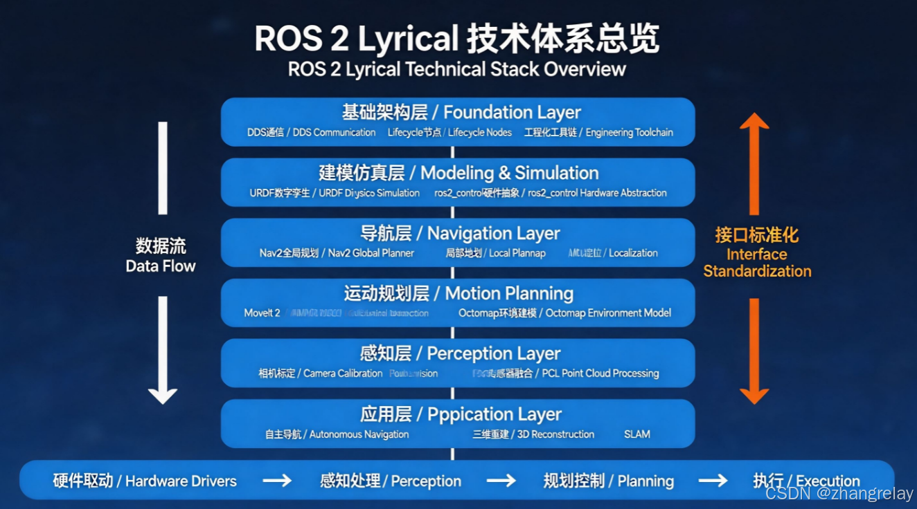
本教程1-10章构建了ROS 2 Lyrical版本下完整的移动操作机器人技术栈,遵循「底层系统-建模仿真-运动执行-环境感知-决策规划」的机器人技术经典分层架构,从最基础的分布式通信机制到三维点云高级处理算法,从纯软件数字仿真到实体硬件驱动部署,形成了理论原理、工程实现、实操验证三位一体的标准化知识体系。
整个技术体系的核心设计主线是模块化、插件化、接口标准化:所有功能模块通过DDS通信中间件实现进程解耦,通过统一消息定义实现跨模块互操作,通过插件机制支持算法无缝替换。这一设计思想贯穿了从底层驱动到上层规划的全部层级,也是ROS生态能够成为全球机器人行业事实标准的核心底层逻辑。
二、分层技术硬核综述
2.1 基础架构层:分布式通信与工程化开发体系(第1-3章)
这一部分是ROS 2的技术基石,核心解决两个本质问题:分布式多进程如何实现可靠确定性通信,以及大型机器人项目如何进行工程化组织。
- 通信中间件的代际跃迁
ROS 2彻底抛弃ROS1自研的TCP/UDP混合通信层,全面拥抱DDS工业级数据分发服务,基于RTPS协议实现发布-订阅通信范式。这一升级带来了三项本质能力提升:- 确定性QoS保障:支持可靠性、持久性、截止时间、生命周期等多维度服务质量配置,可适配硬实时工业控制场景;
- 原生分布式架构:无中心化主节点,多主机对等通信,天然支持多机器人协同与分布式部署;
- 工业级可靠性:DDS协议经过航空航天、国防工业数十年验证,数据分发的确定性、容错性远高于ROS1自研协议。
教程中涉及的话题、服务、动作三种通信范式,对应机器人系统三类典型交互模式:单向高频数据流(话题,适配传感器数据、控制指令)、双向同步调用(服务,适配参数配置、触发指令)、可抢占长时任务(动作,适配导航、运动规划等耗时操作),是ROS生态十几年工程沉淀形成的最佳通信抽象。
- 工程化工具链的标准化
colcon增量编译系统、Python Launch启动框架、rqt调试工具集、RViz2可视化平台,共同构成大型机器人项目的工程支撑。其中生命周期节点(Lifecycle Node)的引入,定义了配置、激活、去激活、清理、销毁的标准状态机,解决了ROS1节点启动顺序混乱、依赖无法管理的工业级痛点,是量产机器人系统的必备特性。
2.2 建模仿真层:数字孪生与硬件抽象(第4-5章)
这一部分的核心价值是在物理世界之外构建可复现、可遍历的数字验证环境,是机器人算法快速迭代的基础底座。
- URDF机器人数字孪生标准
URDF通过XML格式统一了机器人连杆、关节、传感器的几何、物理、视觉描述,是整个ROS生态的「机器人数字孪生接口标准」。Xacro宏语言则解决了URDF代码冗余、参数化能力弱的问题,通过宏定义、参数传递、数学计算,实现机器人模型的模块化、可配置化构建。
所有模型遵循URDF标准的核心意义在于一次建模,全栈复用:差速底盘、机械臂、传感器模型可以无缝接入导航、运动规划、仿真等所有上层工具链,无需重复开发适配,这就是接口标准化的工程价值。 - 物理仿真与硬件抽象的解耦设计
Gazebo物理引擎提供刚体动力学、碰撞检测、传感器噪声仿真能力,能够模拟真实世界的摩擦、重力、惯性、光照,使得算法在仿真环境中的验证结果具备物理参考性。ros2_control框架则是连接仿真与真实硬件的关键中间层:它定义了标准的硬件接口(位置、速度、力控)与控制器接口(关节轨迹控制器、差速驱动控制器等),实现了「上层算法完全一致,底层硬件无缝切换」。同一套导航/运动规划代码,在Gazebo仿真和真实机器人上无需修改,仅需替换硬件接口实现,极大降低了从仿真到实机的迁移成本,是现代机器人开发的标准范式。
2.3 导航层:自主移动的决策与控制系统(第6章 Nav2)
Nav2是ROS 2移动机器人导航的官方标准框架,是移动机器人领域技术成熟度最高、工业应用最广的算法集合,本质是一个基于行为树的分层式导航决策系统。
- 分层导航架构的技术逻辑
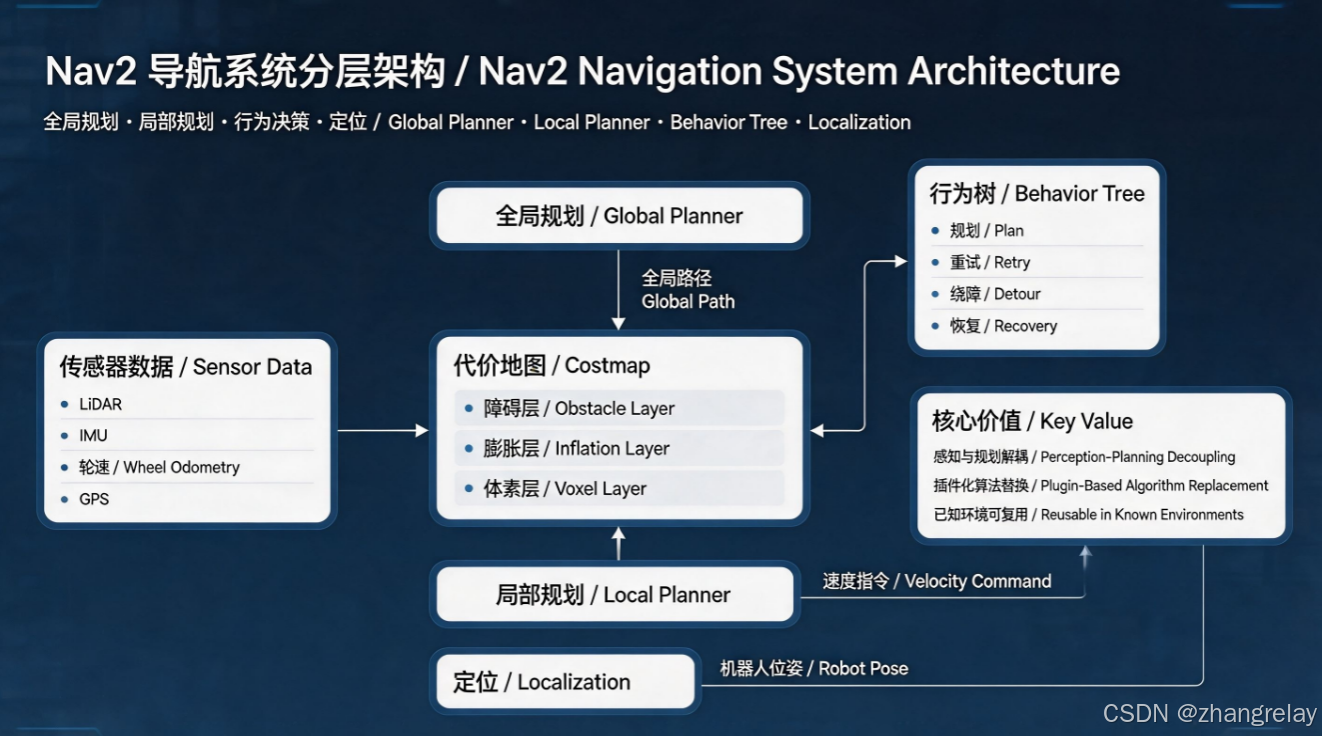
Nav2采用「全局规划-局部规划-行为决策-定位感知」的经典四层架构,每一层职责单一、接口清晰:- 全局规划层:基于Dijkstra/A*算法,在全局代价地图上搜索起点到终点的最优几何路径,负责大尺度路径决策,保证路径全局最优;
- 局部规划层:基于DWB动态窗口法,在局部代价地图上结合机器人运动学约束生成实时速度指令,负责动态避障与轨迹跟踪,保证运动的安全性和平滑性;
- 行为决策层:基于行为树管理导航全生命周期的状态切换(规划、重试、绕障、失败恢复),解决复杂场景下的异常处理问题;
- 定位层:AMCL自适应蒙特卡洛定位,基于粒子滤波算法匹配激光雷达数据与先验地图,实现已知环境中的全局位姿估计。
- 代价地图的感知-规划解耦思想
代价地图是导航系统的核心数据结构,将激光雷达、深度相机、超声波等多传感器的障碍物信息,融合为统一的栅格代价地图;通过膨胀层、障碍层、体素层等插件化机制,实现不同传感器数据的无缝接入。
这种设计的核心价值是感知与规划彻底解耦:规划算法只需要面对统一的代价地图,无需关心底层传感器类型,这也是导航框架能够适配各类机器人硬件与场景的核心原因。 - 插件化设计的工程价值
Nav2所有核心模块均采用插件化设计:全局规划器、局部规划器、代价地图层、恢复行为均可通过配置文件替换。用户可根据场景选择不同算法(如全局规划替换为SBPL、Lattice Planner,局部规划替换为TEB),无需修改框架代码。这种「接口标准化、实现插件化」的设计,是工业级软件框架的典型特征,兼顾了通用性与定制化需求。
2.4 运动规划层:机械臂操作的轨迹生成与碰撞安全(第7章 MoveIt 2)
MoveIt 2是机械臂运动规划的事实标准框架,整合运动学求解、轨迹规划、碰撞检测、抓取操作四大核心能力,是工业机械臂、协作机器人开发的核心工具。
- 运动规划的核心技术流水线
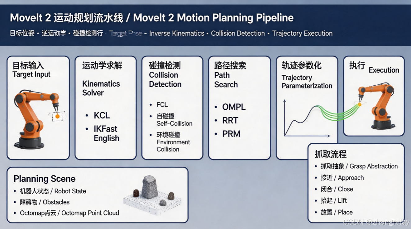
MoveIt 2的核心是move_group节点,其内部处理流水线为:目标位姿输入 → 逆运动学求解 → 碰撞检测校验 → 采样式路径搜索 → 轨迹时间参数化 → 轨迹输出执行。- 逆运动学:默认采用KDL数值迭代解法,适配任意构型机械臂;高精度高速场景可替换为IKFast解析解法,求解速度提升两个数量级;
- 碰撞检测:基于FCL弹性碰撞库,支持网格、基本体、点云、Octomap多种碰撞体类型,实现机械臂自身、环境障碍物、夹持物体的全链路碰撞校验;
- 运动规划:默认集成OMPL开源运动规划库,提供RRT、PRM等多种采样式规划算法,能够在高维构型空间中快速搜索无碰路径,是解决多自由度机械臂规划问题的主流技术路线。
- 规划场景的环境建模能力
Planning Scene规划场景是MoveIt 2的核心数据结构,维护机器人状态、环境障碍物、点云地图的全量信息。它支持两种环境建模模式:- 结构化模式:手动添加几何障碍物,适配工业产线等已知固定场景;
- 感知驱动模式:接入深度相机点云,通过Octomap八叉树地图实时更新动态环境,适配非结构化未知场景。
双模式设计使得MoveIt 2既可以用于高精度工业场景,也可以用于服务机器人的动态环境操作。
- 抓取操作的标准化抽象
Pick&Place抓取放置任务被抽象为标准的Pickup/Place Action接口,整合接近位姿、抓取位姿、夹持闭合、抬起撤退的完整动作序列。配合抓取位姿生成器,可自动生成多组候选抓取姿态,通过规划成功率筛选最优解,大幅提升抓取任务的鲁棒性。
2.5 硬件驱动层:机器人与物理世界的交互接口(第8章 传感器与执行器)
这一部分是连接数字系统与物理世界的桥梁,核心目标是将异构硬件统一抽象为ROS标准消息接口,实现上层算法的硬件无关性。
- 硬件接入的分层范式
教程覆盖了从低速IO到高速传感器的完整硬件接入方案,形成清晰的技术分层:- 简单IO扩展层:Arduino + rosserial方案,实现低成本数字IO、模拟量采集、低速电机控制,适合原型验证与教育场景;
- 运动执行层:差速底盘通过
ros2_control接入,编码器反馈实现PID闭环控制,输出标准Twist控制指令与Odometry里程计信息; - 状态感知层:IMU、GPS、激光雷达、深度相机等传感器,均通过官方驱动节点输出标准消息(
Imu、NavSatFix、LaserScan、PointCloud2)。
所有硬件最终收敛到统一的ROS标准消息,上层导航、规划、感知算法完全不关心硬件型号,实现了软硬件的彻底解耦。
- 多传感器融合的定位体系
教程中涉及的轮式编码器、IMU、GPS,构成了移动机器人定位的多源数据体系,通过robot_localization包的EKF扩展卡尔曼滤波进行融合。这是工业界最常用的组合定位方案:轮式编码器提供短时间高精度的里程增量,IMU提供高频姿态与加速度,GPS提供全局绝对位置约束,三者融合后兼顾了局部精度与全局一致性,解决了单一传感器的固有缺陷(轮式里程计打滑漂移、IMU零漂、GPS丢星)。
2.6 视觉感知层:从像素到语义的环境理解(第9章 计算机视觉)
计算机视觉为机器人提供像素级的环境感知能力,ROS 2通过标准化图像管道,实现了从原始图像到高级视觉算法的完整技术链路。
- 标准化图像处理管道
image_proc/stereo_image_proc构成了ROS视觉的基础处理流水线:原始RAW图像经过去拜耳、畸变校正、色彩转换,输出标准的灰度/彩色校正图像;双目系统进一步计算视差图,生成三维点云。整个流水线完全插件化,参数支持动态重配置,无需用户重复开发基础图像处理代码。
相机标定是所有视觉任务的前置基础,基于张正友标定法求解相机内参与畸变系数,是视觉测量、三维重建、视觉里程计精度的核心保障。教程中强调的重投影误差、极线误差等量化指标,是工程中评判标定质量的硬性标准。 - OpenCV生态的无缝衔接
cv_bridge作为ROS图像与OpenCV格式的桥梁,实现了ROS生态与整个计算机视觉社区的无缝衔接。所有OpenCV原生算法(特征匹配、目标检测、图像分割、单应性计算)均可通过cv_bridge快速迁移到ROS系统,使得ROS视觉开发可以直接复用CV领域全部技术成果,无需重复造轮子。 - 视觉里程计的技术路线
教程中介绍的viso2双目视觉里程计、fovis RGBD视觉里程计,代表了纯视觉定位的经典技术路线:通过相邻帧特征点匹配求解相机运动,实现无GPS环境下的六自由度位姿估计。其核心价值是为激光雷达失效场景(长走廊、开阔无特征环境)提供冗余定位,也是视觉SLAM的基础模块。
2.7 三维感知层:点云处理与空间建模(第10章 PCL点云库)
点云是机器人三维环境感知的核心数据形式,PCL库是三维点云处理的事实标准,为机器人提供了从原始点云到结构化环境信息的完整处理能力。
- 点云处理的标准预处理流水线
教程中构建的「原始点云 → 统计滤波去噪 → 体素栅格降采样 → 高级处理」流水线,是工业级点云处理的标准前置流程:- 统计滤波:基于邻域距离的高斯分布统计剔除离群噪声点,解决传感器散粒噪声问题;
- 体素降采样:通过三维栅格重心化,在保留结构特征的前提下大幅降低点数,平衡算法精度与算力消耗。
这两步预处理是所有高级点云算法的基础,直接决定了后续分割、配准的精度与速度。
- 核心算法的技术本质
- ICP迭代最近点配准:通过对应点迭代求解刚体变换,实现多帧点云对齐,是三维重建、SLAM回环检测的核心算法;本质是最小二乘优化在点云配准问题上的应用,适合初始偏差较小的场景,大偏差需结合特征匹配提供初值。
- RANSAC平面分割:通过随机抽样一致性算法拟合几何模型,鲁棒提取地面、墙面等结构化平面,是移动机器人地面分割、障碍物检测的核心算法;核心优势是对离群点不敏感,适配噪声较大的真实传感器数据。
- 八叉树空间索引:通过层级化三维空间划分,将线性点云转化为树形结构,将邻域搜索的时间复杂度从O(n)降至O(logn),是大规模点云碰撞检测、空间查询的性能基础。
- 算法库的工程化设计
PCL库所有算法均遵循「设置输入 → 配置参数 → 执行计算 → 获取输出」的统一调用范式,这种一致性设计大幅降低了学习成本,开发者掌握一种算法后可以快速迁移到其他算法,是大型算法库工程化设计的典范。
三、进阶学习展望
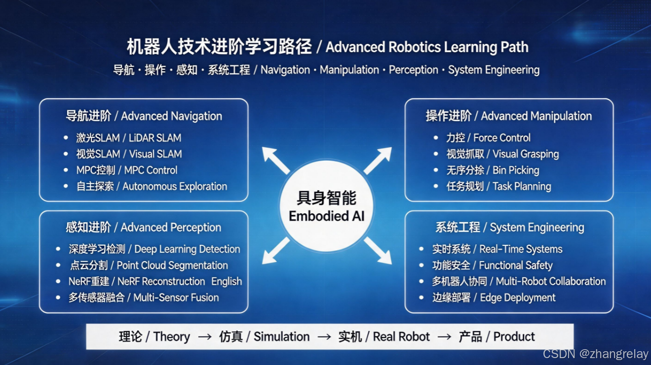
完成本教程10章内容后,已掌握移动操作机器人的全栈基础能力,后续可根据应用方向向以下四个维度深入进阶,逐步触及机器人技术的前沿领域。
3.1 移动机器人导航进阶
- SLAM同步定位与建图
教程中导航基于已知先验地图,未知环境下的自主建图是更核心的能力。进阶方向包括:激光SLAM(Cartographer、LIO-SAM)、视觉SLAM(ORB-SLAM3、RTAB-Map)、多传感器融合SLAM;重点学习图优化、回环检测、因子图优化等核心理论,掌握从原始传感器数据到全局一致性地图的完整技术链路。 - 高级规划算法
深入学习TEB弹性带算法、MPC模型预测控制等局部规划器,提升轨迹平滑性与动态避障能力;全局规划层面学习混合A*、状态格规划等考虑运动学约束的规划算法,适配差速、阿克曼、全向轮等不同底盘构型。 - 复杂场景导航
学习多层地图、拓扑导航、多楼层导航,适配大型建筑场景;学习动态障碍物预测与速度障碍法(VO),提升人流密集场景的导航表现;探索自主探索建图(Exploration),实现机器人在未知环境中的自主遍历与地图构建。
3.2 机械臂操作进阶
- 高级运动规划与力控
深入学习CHOMP、STOMP等基于优化的规划算法,提升轨迹平滑性;学习笛卡尔空间约束规划(如保持水平姿态搬运),适配复杂工业工艺;探索力控柔顺控制,结合力矩传感器实现装配、打磨等接触类操作任务。 - 视觉抓取与三维感知
结合深度学习实现通用物体抓取检测、6-DoF位姿估计,从结构化场景抓取升级到非结构化未知物体抓取;学习点云配准、三维物体识别,实现散乱工件的无序抓取(Bin Picking),这是工业3D视觉的核心应用场景。 - 任务规划与编程范式
学习任务规划语言(如PDDL),实现多步骤复杂作业任务的自动编排;探索无代码拖拽式机器人编程,降低工业机器人使用门槛;研究人机协作安全机制,保障人机共融场景下的运行安全。
3.3 感知与融合进阶
- 多传感器紧耦合融合
深入学习卡尔曼滤波、粒子滤波、因子图优化等多源融合理论,实现激光、视觉、IMU、轮速、GPS的紧耦合融合定位,提升复杂环境下的定位鲁棒性;学习多传感器时空标定技术,解决不同传感器的时间同步、空间校准问题,这是融合系统精度的核心瓶颈。 - 深度学习视觉感知
将YOLO、SAM等深度学习目标检测、分割模型部署到ROS 2系统中,实现像素级语义环境理解;学习端到端视觉导航,通过深度强化学习实现从图像直接输出控制指令的端到端控制。 - 三维重建与数字孪生
深入学习TSDF、NeRF等三维重建技术,实现环境的高精度三维模型构建;结合数字孪生技术,实现真实机器人与虚拟仿真环境的实时映射,用于远程监控、算法仿真、故障预判。
3.4 系统工程与前沿方向
- 实时系统与功能安全
学习ROS 2实时性优化:搭配PREEMPT_RT实时内核、配置DDS实时QoS、优化节点调度,满足工业场景的硬实时要求;学习ISO 26262、ISO 13849等功能安全标准,设计安全监控、故障诊断、安全停机机制,保障量产机器人的可靠性。 - 多机器人协同
探索多机器人分布式协同:分布式SLAM、协同导航、任务分配;学习ROS 2的DDS大网络配置,实现跨设备、跨场地的多机协同作业,适配仓储物流、集群巡检等场景。 - 边缘部署与算力优化
学习嵌入式ROS 2部署:在Jetson、瑞芯微等边缘平台上优化节点性能;研究算法轻量化、模型量化、硬件加速,在有限算力下实现实时感知与规划。 - 具身智能前沿
关注具身智能(Embodied AI)技术方向:将大语言模型与ROS机器人结合,实现自然语言指令的任务理解与执行;探索强化学习在机器人控制中的应用,实现复杂环境下的自适应运动与操作。
四、总结
本教程10章内容搭建了机器人开发的「标准技术脚手架」,覆盖了从底层通信到上层感知规划的全部核心模块。但机器人技术是一门高度交叉的应用学科,理论、仿真、实机三者迭代推进,才能逐步构建起完整的工程能力。
整个ROS生态的核心魅力在于其标准化的接口与开放的社区生态,它让开发者可以站在全行业的技术积累之上解决具体场景问题,而非重复造轮子。掌握本教程内容后,开发者已具备独立开发完整移动操作机器人的基础能力,后续可结合具体行业场景深耕细分方向,逐步向系统架构师、算法专家的方向进阶。
A Hardcore Technical Review of the Full ROS 2 Lyrical Technology Stack and Outlook for Advanced Learning
I. Overview of the Technical System
Chapters 1 to 10 of this tutorial build a complete technology stack for mobile manipulator robots under the ROS 2 Lyrical distribution, following the classic layered architecture of robotics: underlying system, modeling and simulation, motion execution, environment perception, and decision-making planning. From basic distributed communication mechanisms to advanced 3D point cloud processing algorithms, from pure software digital simulation to physical hardware driver deployment, the tutorial forms a standardized knowledge system integrating theoretical principles, engineering implementation, and practical verification.
The core design thread running through the entire technical system is modularity, pluginization, and interface standardization. All functional modules achieve process decoupling through the DDS communication middleware, realize cross-module interoperability through unified message definitions, and support seamless algorithm replacement through the plugin mechanism. This design philosophy runs through all levels from underlying drivers to high-level planning, and is also the core underlying logic that enables the ROS ecosystem to become the de facto standard in the global robotics industry.
II. In-Depth Technical Review by Layers
2.1 Foundation Architecture Layer: Distributed Communication and Engineering Development System (Chapters 1–3)
This part constitutes the technical cornerstone of ROS 2, which essentially solves two core problems: how to achieve reliable and deterministic communication in distributed multi-process systems, and how to organize large-scale robotics projects in an engineering manner.
-
Generational Leap in Communication Middleware
ROS 2 completely abandons the self-developed TCP/UDP hybrid communication layer of ROS 1, and fully embraces DDS (Data Distribution Service), an industrial-grade data distribution service, to implement the publish-subscribe communication paradigm based on the RTPS protocol. This upgrade brings three essential capability improvements:- Deterministic QoS Guarantee: It supports multi-dimensional quality of service configurations such as reliability, durability, deadline, and lifecycle, and can adapt to hard real-time industrial control scenarios.
- Native Distributed Architecture: With no centralized master node and peer-to-peer multi-host communication, it natively supports multi-robot collaboration and distributed deployment.
- Industrial-Grade Reliability: The DDS protocol has been verified by decades of applications in aerospace and national defense industries, and its determinism and fault tolerance in data distribution are far superior to the self-developed protocol of ROS 1.
The three communication paradigms covered in the tutorial — topic, service, and action — correspond to three typical interaction modes in robotic systems: one-way high-frequency data streams (topics, suitable for sensor data and control commands), two-way synchronous calls (services, suitable for parameter configuration and trigger commands), and preemptible long-duration tasks (actions, suitable for time-consuming operations such as navigation and motion planning). They are the best communication abstractions formed by more than ten years of engineering practice in the ROS ecosystem.
-
Standardization of Engineering Toolchain
The colcon incremental build system, Python Launch startup framework, rqt debugging toolset, and RViz2 visualization platform together form the engineering support for large-scale robotics projects. Among them, the introduction of Lifecycle Nodes defines a standard state machine of configuring, activating, deactivating, cleaning up, and destroying, which solves the industrial pain points of chaotic node startup sequence and unmanageable dependencies in ROS 1, and is an essential feature for mass-produced robotic systems.
2.2 Modeling and Simulation Layer: Digital Twin and Hardware Abstraction (Chapters 4–5)
The core value of this part is to build a reproducible and traversable digital verification environment outside the physical world, which is the basic foundation for rapid iteration of robotics algorithms.
-
URDF as the Standard for Robot Digital Twin
URDF unifies the geometric, physical, and visual descriptions of robot links, joints, and sensors in XML format, and serves as the “interface standard for robot digital twins” in the entire ROS ecosystem. The Xacro macro language solves the problems of redundant code and weak parameterization ability of URDF, and realizes modular and configurable construction of robot models through macro definitions, parameter passing, and mathematical calculations.The core significance of all models following the URDF standard is “model once, reuse everywhere”: models of differential drive chassis, manipulators, and sensors can be seamlessly connected to all upper-level toolchains such as navigation, motion planning, and simulation without repeated development and adaptation — this is the engineering value of interface standardization.
-
Decoupled Design of Physical Simulation and Hardware Abstraction
The Gazebo physics engine provides rigid body dynamics, collision detection, and sensor noise simulation capabilities, and can simulate friction, gravity, inertia, and lighting in the real world, so that the verification results of algorithms in the simulation environment have physical reference value.The
ros2_controlframework is the key middle layer connecting simulation and real hardware. It defines standard hardware interfaces (position, velocity, force control) and controller interfaces (joint trajectory controller, differential drive controller, etc.), realizing that upper-level algorithms are completely consistent, and underlying hardware can be switched seamlessly. The same set of navigation/motion planning code does not need to be modified in Gazebo simulation or on a real robot; only the hardware interface implementation needs to be replaced. This greatly reduces the migration cost from simulation to real robots, and is the standard paradigm of modern robot development.
2.3 Navigation Layer: Decision and Control System for Autonomous Mobility (Chapter 6: Nav2)
Nav2 is the official standard framework for mobile robot navigation in ROS 2. It is the most technologically mature and widely used algorithm set in the field of mobile robots, and is essentially a hierarchical navigation decision-making system based on behavior trees.
-
Technical Logic of Hierarchical Navigation Architecture
Nav2 adopts the classic four-layer architecture of “global planning – local planning – behavior decision – localization and perception”, with each layer having a single responsibility and clear interfaces:- Global planning layer: Based on Dijkstra/A* algorithms, it searches for the optimal geometric path from the start point to the end point on the global costmap, responsible for large-scale path decision-making and ensuring global optimality.
- Local planning layer: Based on the DWB (Dynamic Window Approach) algorithm, it generates real-time velocity commands combined with robot kinematic constraints on the local costmap, responsible for dynamic obstacle avoidance and trajectory tracking, and ensuring motion safety and smoothness.
- Behavior decision layer: It manages state switching throughout the navigation lifecycle (planning, retry, obstacle detour, failure recovery) based on behavior trees, and solves the problem of exception handling in complex scenarios.
- Localization layer: AMCL (Adaptive Monte Carlo Localization), based on the particle filter algorithm, matches LiDAR data with a prior map to realize global pose estimation in known environments.
-
Idea of Perception-Planning Decoupling via Costmaps
The costmap is the core data structure of the navigation system, which fuses obstacle information from multiple sensors such as LiDAR, depth cameras, and ultrasonic sensors into a unified grid costmap. Through plugin-based mechanisms such as inflation layer, obstacle layer, and voxel layer, seamless access to different sensor data is realized.The core value of this design is the complete decoupling of perception and planning: planning algorithms only need to face a unified costmap without caring about the type of underlying sensors. This is also the core reason why the navigation framework can adapt to various robot hardware and scenarios.
-
Engineering Value of Plugin-Based Design
All core modules of Nav2 adopt a plugin-based design: global planners, local planners, costmap layers, and recovery behaviors can all be replaced through configuration files. Users can select different algorithms according to scenarios (e.g., replace global planning with SBPL or Lattice Planner, and local planning with TEB) without modifying the framework code. This design of “standardized interfaces and plugin-based implementations” is a typical feature of industrial-grade software frameworks, balancing versatility and customization requirements.
2.4 Motion Planning Layer: Trajectory Generation and Collision Safety for Manipulator Operation (Chapter 7: MoveIt 2)
MoveIt 2 is the de facto standard framework for manipulator motion planning. It integrates four core capabilities: kinematics solving, trajectory planning, collision detection, and grasping operation, and is the core tool for the development of industrial manipulators and collaborative robots.
-
Core Processing Pipeline of Motion Planning
The core of MoveIt 2 is themove_groupnode, and its internal processing pipeline is: target pose input → inverse kinematics solving → collision detection verification → sampling-based path search → trajectory time parameterization → trajectory output for execution.- Inverse kinematics: The KDL numerical iterative solver is used by default, adapting to manipulators of any configuration; for high-precision and high-speed scenarios, it can be replaced with the IKFast analytical solver, which increases the solving speed by two orders of magnitude.
- Collision detection: Based on the FCL (Flexible Collision Library), it supports multiple collision body types such as meshes, primitives, point clouds, and Octomaps, realizing full-link collision verification of the manipulator itself, environmental obstacles, and grasped objects.
- Motion planning: The OMPL (Open Motion Planning Library) is integrated by default, providing various sampling-based planning algorithms such as RRT and PRM, which can quickly search for collision-free paths in high-dimensional configuration space, and is the mainstream technical route for solving multi-degree-of-freedom manipulator planning problems.
-
Environment Modeling Capability of the Planning Scene
The Planning Scene is the core data structure of MoveIt 2, which maintains full information of robot states, environmental obstacles, and point cloud maps. It supports two environment modeling modes:- Structured mode: Geometric obstacles are added manually, suitable for known fixed scenarios such as industrial production lines.
- Perception-driven mode: It accesses depth camera point clouds and updates the dynamic environment in real time through the Octomap octree map, suitable for unstructured unknown scenarios.
The dual-mode design enables MoveIt 2 to be used in both high-precision industrial scenarios and dynamic environment operations of service robots.
-
Standardized Abstraction of Grasping Operations
The Pick & Place task is abstracted into standard Pickup/Place Action interfaces, integrating the complete action sequence of approach pose, grasping pose, gripper closing, and lifting retreat. Combined with the grasp pose generator, multiple sets of candidate grasping poses can be automatically generated, and the optimal solution can be screened by planning success rate, which greatly improves the robustness of grasping tasks.
2.5 Hardware Driver Layer: Interactive Interface Between Robots and the Physical World (Chapter 8: Sensors and Actuators)
This part serves as the bridge connecting the digital system and the physical world, with the core goal of uniformly abstracting heterogeneous hardware into ROS standard message interfaces, realizing hardware independence of upper-level algorithms.
-
Hierarchical Paradigm of Hardware Access
The tutorial covers a complete hardware access scheme from low-speed I/O to high-speed sensors, forming a clear technical hierarchy:- Simple I/O expansion layer: Arduino + rosserial solution, realizing low-cost digital I/O, analog acquisition, and low-speed motor control, suitable for prototype verification and educational scenarios.
- Motion execution layer: The differential drive chassis is accessed through
ros2_control, and encoder feedback realizes PID closed-loop control, outputting standardTwistcontrol commands andOdometryodometry information. - State perception layer: Sensors such as IMU, GPS, LiDAR, and depth cameras all output standard messages (
Imu,NavSatFix,LaserScan,PointCloud2) through official driver nodes.
All hardware eventually converges to unified ROS standard messages, and upper-level navigation, planning, and perception algorithms are completely independent of hardware models, realizing complete decoupling of software and hardware.
-
Positioning System with Multi-Sensor Fusion
The wheel encoders, IMU, and GPS involved in the tutorial constitute a multi-source data system for mobile robot positioning, which is fused through the EKF (Extended Kalman Filter) of therobot_localizationpackage. This is the most commonly used integrated positioning solution in the industry: wheel encoders provide high-precision odometry increments in a short time, IMU provides high-frequency attitude and acceleration, and GPS provides global absolute position constraints. The combination of the three balances local accuracy and global consistency, and solves the inherent defects of a single sensor (slippage drift of wheel odometry, IMU zero drift, GPS signal loss).
2.6 Visual Perception Layer: Environment Understanding from Pixels to Semantics (Chapter 9: Computer Vision)
Computer vision provides robots with pixel-level environment perception capabilities. ROS 2 realizes a complete technical link from raw images to advanced vision algorithms through a standardized image pipeline.
-
Standardized Image Processing Pipeline
image_proc/stereo_image_procconstitutes the basic processing pipeline of ROS vision: raw RAW images are debayered, distortion-corrected, and color-converted to output standard grayscale/color corrected images; binocular systems further calculate disparity maps and generate 3D point clouds. The entire pipeline is fully plugin-based, and parameters support dynamic reconfiguration, eliminating the need for users to repeatedly develop basic image processing code.Camera calibration is the prerequisite for all vision tasks. Based on Zhang’s calibration method, it solves the camera intrinsic parameters and distortion coefficients, and is the core guarantee for the accuracy of visual measurement, 3D reconstruction, and visual odometry. Quantitative indicators such as reprojection error and epipolar error emphasized in the tutorial are rigid standards for judging calibration quality in engineering.
-
Seamless Connection with the OpenCV Ecosystem
As a bridge between ROS images and OpenCV formats,cv_bridgerealizes the seamless connection between the ROS ecosystem and the entire computer vision community. All native OpenCV algorithms (feature matching, object detection, image segmentation, homography calculation) can be quickly migrated to ROS systems throughcv_bridge, so that ROS vision development can directly reuse all technical achievements in the CV field without reinventing the wheel. -
Technical Route of Visual Odometry
The viso2 stereo visual odometry and fovis RGBD visual odometry introduced in the tutorial represent the classic technical route of pure visual positioning: the camera motion is solved by matching feature points of adjacent frames to realize 6-DOF pose estimation in GPS-denied environments. Its core value is to provide redundant positioning for scenarios where LiDAR fails (long corridors, open featureless environments), and it is also the basic module of visual SLAM.
2.7 3D Perception Layer: Point Cloud Processing and Spatial Modeling (Chapter 10: PCL Point Cloud Library)
Point cloud is the core data form of robot 3D environment perception. The PCL library is the de facto standard for 3D point cloud processing, providing robots with complete processing capabilities from raw point clouds to structured environment information.
-
Standard Preprocessing Pipeline for Point Cloud Processing
The “raw point cloud → statistical outlier removal → voxel grid downsampling → advanced processing” pipeline constructed in the tutorial is the standard preprocessing flow for industrial-grade point cloud processing:- Statistical filtering: It removes outlier noise points based on the Gaussian distribution of neighborhood distances, solving the problem of sensor shot noise.
- Voxel downsampling: Through 3D grid centroidization, the number of points is greatly reduced while retaining structural features, balancing algorithm accuracy and computing power consumption.
These two steps of preprocessing are the basis of all advanced point cloud algorithms, and directly determine the accuracy and speed of subsequent segmentation and registration.
-
Technical Essence of Core Algorithms
- ICP (Iterative Closest Point) registration: It solves rigid body transformation through corresponding point iteration to realize multi-frame point cloud alignment, and is the core algorithm of 3D reconstruction and SLAM loop closure detection. Essentially, it is the application of least squares optimization in point cloud registration problems, suitable for scenarios with small initial deviations; for large deviations, feature matching is required to provide initial values.
- RANSAC (Random Sample Consensus) plane segmentation: It fits geometric models through the random sample consensus algorithm, and robustly extracts structured planes such as the ground and walls. It is the core algorithm for mobile robot ground segmentation and obstacle detection; its core advantage is insensitivity to outliers and adaptation to noisy real sensor data.
- Octree spatial indexing: Through hierarchical 3D space division, linear point clouds are transformed into a tree structure, reducing the time complexity of neighborhood search from O(n) to O(logn), which is the performance basis for large-scale point cloud collision detection and spatial query.
-
Engineering Design of the Algorithm Library
All algorithms in the PCL library follow the unified calling paradigm of “set input → configure parameters → execute calculation → get output”. This consistent design greatly reduces the learning cost. After mastering one algorithm, developers can quickly migrate to other algorithms, which is a model of engineering design for large-scale algorithm libraries.
III. Outlook for Advanced Learning
After completing the 10 chapters of this tutorial, you will have mastered the full-stack basic capabilities of mobile manipulator robots. In the follow-up, you can deepen your advanced learning in the following four dimensions according to the application direction, and gradually reach the cutting-edge field of robotics technology.
3.1 Advanced Mobile Robot Navigation
-
SLAM (Simultaneous Localization and Mapping)
Navigation in the tutorial is based on known prior maps, and autonomous mapping in unknown environments is a more core capability. Advanced directions include: LiDAR SLAM (Cartographer, LIO-SAM), visual SLAM (ORB-SLAM3, RTAB-Map), and multi-sensor fusion SLAM. Focus on learning core theories such as graph optimization, loop closure detection, and factor graph optimization, and master the complete technical link from raw sensor data to globally consistent maps. -
Advanced Planning Algorithms
In-depth study of local planners such as the TEB (Time Elastic Band) algorithm and MPC (Model Predictive Control) to improve trajectory smoothness and dynamic obstacle avoidance capability; at the global planning level, learn kinematically constrained planning algorithms such as Hybrid A* and state lattice planning to adapt to different chassis configurations such as differential drive, Ackermann steering, and omnidirectional wheels. -
Navigation in Complex Scenarios
Learn multi-layer maps, topological navigation, and multi-floor navigation to adapt to large building scenarios; learn dynamic obstacle prediction and the Velocity Obstacle (VO) method to improve navigation performance in crowded scenarios; explore autonomous exploration mapping to realize autonomous traversal and map construction of robots in unknown environments.
3.2 Advanced Manipulator Operation
-
Advanced Motion Planning and Force Control
In-depth study of optimization-based planning algorithms such as CHOMP and STOMP to improve trajectory smoothness; learn Cartesian space constrained planning (e.g., keeping horizontal posture during handling) to adapt to complex industrial processes; explore force-controlled compliant control combined with torque sensors to realize contact operation tasks such as assembly and grinding. -
Visual Grasping and 3D Perception
Combine deep learning to realize general object grasping detection and 6-DoF pose estimation, upgrading from structured scene grasping to unstructured unknown object grasping; learn point cloud registration and 3D object recognition to realize bin picking of scattered workpieces, which is the core application scenario of industrial 3D vision. -
Task Planning and Programming Paradigms
Learn task planning languages (such as PDDL) to realize automatic编排 of multi-step complex operation tasks; explore no-code drag-and-drop robot programming to reduce the threshold of industrial robot use; study human-robot collaboration safety mechanisms to ensure operational safety in human-robot coexistence scenarios.
3.3 Advanced Perception and Fusion
-
Tight-Coupled Multi-Sensor Fusion
In-depth study of multi-source fusion theories such as Kalman filter, particle filter, and factor graph optimization to realize tight-coupled fusion positioning of LiDAR, vision, IMU, wheel speed, and GPS, and improve positioning robustness in complex environments; learn multi-sensor spatiotemporal calibration technology to solve the problems of time synchronization and spatial calibration of different sensors, which is the core bottleneck of fusion system accuracy. -
Deep Learning Visual Perception
Deploy deep learning object detection and segmentation models such as YOLO and SAM into ROS 2 systems to realize pixel-level semantic environment understanding; learn end-to-end visual navigation, and realize end-to-end control from images directly to control commands through deep reinforcement learning. -
3D Reconstruction and Digital Twin
In-depth study of 3D reconstruction technologies such as TSDF and NeRF to realize high-precision 3D model construction of the environment; combine digital twin technology to realize real-time mapping between real robots and virtual simulation environments, which is used for remote monitoring, algorithm simulation, and fault prediction.
3.4 System Engineering and Cutting-Edge Directions
-
Real-Time Systems and Functional Safety
Learn ROS 2 real-time optimization: match the PREEMPT_RT real-time kernel, configure DDS real-time QoS, and optimize node scheduling to meet the hard real-time requirements of industrial scenarios; learn functional safety standards such as ISO 26262 and ISO 13849, and design safety monitoring, fault diagnosis, and safe shutdown mechanisms to ensure the reliability of mass-produced robots. -
Multi-Robot Coordination
Explore distributed collaboration of multiple robots: distributed SLAM, collaborative navigation, and task allocation; learn the DDS large network configuration of ROS 2 to realize multi-machine collaborative operations across devices and sites, adapting to scenarios such as warehousing logistics and cluster inspection. -
Edge Deployment and Computing Power Optimization
Learn embedded ROS 2 deployment: optimize node performance on edge platforms such as Jetson and Rockchip; research algorithm lightweighting, model quantization, and hardware acceleration to realize real-time perception and planning under limited computing power. -
Cutting-Edge Embodied AI
Pay attention to the technical direction of embodied AI: combine large language models with ROS robots to realize task understanding and execution of natural language instructions; explore the application of reinforcement learning in robot control to realize adaptive motion and operation in complex environments.
IV. Conclusion
The 10 chapters of this tutorial build a “standard technical scaffold” for robot development, covering all core modules from underlying communication to high-level perception and planning. However, robotics is a highly interdisciplinary applied discipline. Only through the iterative advancement of theory, simulation, and real-world testing can a complete set of engineering capabilities be gradually built.
The core charm of the entire ROS ecosystem lies in its standardized interfaces and open community ecology, which allows developers to solve specific scenario problems on the basis of the technical accumulation of the entire industry, instead of reinventing the wheel. After mastering the content of this tutorial, developers already have the basic ability to independently develop complete mobile manipulator robots. In the follow-up, they can deepen their expertise in subdivided directions combined with specific industry scenarios, and gradually advance to the direction of system architects and algorithm experts.
| 序号 | 文章链接 |
|---|---|
| 0 | https://blog.csdn.net/ZhangRelay/article/details/163615709 |
| 1 | https://blog.csdn.net/ZhangRelay/article/details/163671171 |
| 2 | https://blog.csdn.net/ZhangRelay/article/details/163671414 |
| 3 | https://blog.csdn.net/ZhangRelay/article/details/163685278 |
| 4 | https://blog.csdn.net/ZhangRelay/article/details/163685667 |
| 5 | https://blog.csdn.net/ZhangRelay/article/details/163758741 |
| 6 | https://blog.csdn.net/ZhangRelay/article/details/163759041 |
| 7 | https://blog.csdn.net/ZhangRelay/article/details/163775108 |
| 8 | https://blog.csdn.net/ZhangRelay/article/details/163775565 |
| 9 | https://blog.csdn.net/ZhangRelay/article/details/163821737 |
| 10 | https://blog.csdn.net/ZhangRelay/article/details/163822211 |

DAMO开发者矩阵,由阿里巴巴达摩院和中国互联网协会联合发起,致力于探讨最前沿的技术趋势与应用成果,搭建高质量的交流与分享平台,推动技术创新与产业应用链接,围绕“人工智能与新型计算”构建开放共享的开发者生态。
更多推荐
 2
2 0
0- 0


 已为社区贡献237条内容

所有评论(0)