单臂路由组网实验
一、实验名称
单臂路由组网实验(思科 Router-on-a-Stick)
二、实验原理
单臂路由:路由器仅使用1 个物理接口,通过创建多个逻辑子接口,搭配 802.1Q 封装,分别对应不同 VLAN,作为各 VLAN 网段网关,实现二层隔离的 VLAN 之间三层互通。
- 二层交换机划分 VLAN,Access 口接终端,上联路由器端口配置 Trunk,承载带 Tag 的多 VLAN 流量;
- 路由器物理接口开启,子接口绑定对应 VLAN ID 并配置网关 IP;
- 同 VLAN 二层转发,跨 VLAN 流量上送到路由器子接口完成三层路由转发。
三、实验组网拓扑说明
1. 设备清单
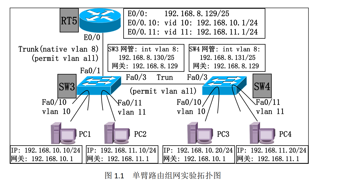
路由器 RT5、二层交换机 SW3、SW4、终端 PC1、PC2、PC3、PC4
2. 链路连接
- RT5 E0/0 ↔ SW3 Fa0/1:Trunk 链路,Native VLAN 8(网管 VLAN)
- SW3 Fa0/3 ↔ SW4 Fa0/3:交换机间 Trunk 链路,允许所有 VLAN
- SW3 Fa0/10:PC1(VLAN10);SW3 Fa0/11:PC2(VLAN11)
- SW4 Fa0/10:PC3(VLAN10);SW4 Fa0/11:PC4(VLAN11)
3. VLAN 与 IP 规划
|
设备 |
所属 VLAN |
IP 地址 / 掩码 |
默认网关 |
|
PC1 |
VLAN10 |
[192.168.10.20/24](192.168.10.20/24) |
[192.168.10.1](192.168.10.1) |
|
PC3 |
VLAN10 |
[192.168.10.10/24](192.168.10.10/24) |
[192.168.10.1](192.168.10.1) |
|
PC2 |
VLAN11 |
[192.168.11.10/24](192.168.11.10/24) |
[192.168.11.1](192.168.11.1) |
|
PC4 |
VLAN11 |
[192.168.11.20/24](192.168.11.20/24) |
[192.168.11.1](192.168.11.1) |
|
RT5 E0/0(Native VLAN8) |
VLAN8 |
[192.168.8.129/25](192.168.8.129/25) |
- |
|
RT5 E0/0.10 |
VLAN10 |
[192.168.10.1/24](192.168.10.1/24)(网关) |
- |
|
RT5 E0/0.11 |
VLAN11 |
[192.168.11.1/24](192.168.11.1/24)(网关) |
- |
|
SW3 管理地址 Vlan8 |
VLAN8 |
[192.168.8.130/25](192.168.8.130/25) |
[192.168.8.129](192.168.8.129) |
|
SW4 管理地址 Vlan8 |
VLAN8 |
[192.168.8.131/25](192.168.8.131/25) |
[192.168.8.129](192.168.8.129) |
4. VLAN 用途
- VLAN8:网管专用 VLAN,承载交换机管理 IP、路由器上联 Native VLAN;
- VLAN10:生产业务 VLAN;
- VLAN11:办公业务 VLAN。
四、实验任务与目标
- 二层隔离、三层全网互通:同 VLAN 二层互通,跨 VLAN 经单臂路由三层可达;
- 区分 VLAN8/10/11 广播域范围,分析二层广播转发边界;
- 梳理 PC1 ping PC4、PC4 ping SW4 网管地址的二层 + 三层完整数据流;
- 掌握交换机 Trunk、Native VLAN、路由器子接口 802.1Q 封装配置;
- 掌握二层交换机管理 VLAN、默认网关配置;
- 熟练使用 show 类命令排查 VLAN、Trunk、三层接口、路由表故障。
五、设备标准化基础配置(路由器 / 交换机通用)
enable
configure terminal
hostname RT5 //交换机改为hostname SW3/SW4
no ip domain-lookup
line console 0
logging synchronous
no login
privilege level 15
line vty 0 4
no login
privilege level 15
exit
六、交换机二层 VLAN 基础配置
6.1 SW3 VLAN 创建
configure terminal
vtp mode transparent
vlan 8
exit
vlan 10
exit
vlan 11
exit
6.2 SW4 VLAN 创建
configure terminal
vtp mode transparent
vlan 8
exit
vlan 10
exit
vlan 11
exit
验证命令
show vlan
七、交换机 Access 接入端口配置
SW3 接入终端接口
! Fa0/10 PC1 VLAN10
interface fastEthernet 0/10
switchport mode access
switchport access vlan 10
exit
! Fa0/11 PC2 VLAN11
interface fastEthernet 0/11
switchport mode access
switchport access vlan 11
exit
SW4 接入终端接口
! Fa0/10 PC3 VLAN10
interface fastEthernet 0/10
switchport mode access
switchport access vlan 10
exit
! Fa0/11 PC4 VLAN11
interface fastEthernet 0/11
switchport mode access
switchport access vlan 11
exit
八、交换机 Trunk 链路配置
8.1 SW3 ↔ SW4 Trunk(Fa0/3)
SW3
interface fastEthernet 0/3
switchport trunk encapsulation dot1q
switchport mode trunk
switchport trunk allowed vlan all
exit
SW4
interface fastEthernet 0/3
switchport trunk encapsulation dot1q
switchport mode trunk
switchport trunk allowed vlan all
exit
8.2 SW3 上联路由器 Trunk(Fa0/1,Native VLAN8)
interface fastEthernet 0/1
switchport trunk encapsulation dot1q
switchport mode trunk
switchport trunk allowed vlan all
switchport trunk native vlan 8
exit
Trunk 验证命令
show interfaces trunk
show interfaces fastEthernet 0/1 switchport
show interfaces fastEthernet 0/3 switchport
九、二层交换机网管地址与默认网关配置
9.1 SW3 管理配置
interface vlan 8
ip address 192.168.8.130 255.255.255.128
no shutdown
exit
ip default-gateway 192.168.8.129
9.2 SW4 管理配置
interface vlan 8
ip address 192.168.8.131 255.255.255.128
no shutdown
exit
ip default-gateway 192.168.8.129
验证命令
show ip interface brief
show running-config
十、路由器单臂路由(子接口)核心配置
! 物理主接口(Native VLAN8网关)
interface Ethernet 0/0
ip address 192.168.8.129 255.255.255.128
no shutdown
exit
! VLAN10子接口
interface Ethernet 0/0.10
encapsulation dot1Q 10
ip address 192.168.10.1 255.255.255.0
no shutdown
exit
! VLAN11子接口
interface Ethernet 0/0.11
encapsulation dot1Q 11
ip address 192.168.11.1 255.255.255.0
no shutdown
exit
路由器三层接口查看命令
show ip interface brief
show interfaces Ethernet 0/0
show ip route
show ip arp
show running-config
故障提示:物理接口 down → 缺少no shutdown;子接口协议 down → 未配置encapsulation dot1q。
十一、全网连通性测试表
|
Ping 源 \ 目标 |
PC1(10.20) |
PC2(11.10) |
PC3(10.10) |
PC4(11.20) |
RT5(8.129) |
SW3(8.130) |
SW4(8.131) |
|
PC1 |
√ |
√ |
√ |
√ |
√ |
√ |
√ |
|
PC2 |
√ |
√ |
√ |
√ |
√ |
√ |
√ |
|
PC3 |
√ |
√ |
√ |
√ |
√ |
√ |
√ |
|
PC4 |
√ |
√ |
√ |
√ |
√ |
√ |
√ |
|
SW3 |
√ |
√ |
√ |
√ |
√ |
√ |
√ |
|
SW4 |
√ |
√ |
√ |
√ |
√ |
√ |
√ |
测试结论
全网全部互通;同 VLAN 流量二层转发,跨 VLAN 流量送至路由器子接口路由转发。
十二、广播域与数据流分析
1. 各 VLAN 广播域范围
- VLAN10 广播帧:仅 SW3、SW4 所有 VLAN10 Access 端口(PC1、PC3)接收,VLAN8、VLAN11 丢弃;Trunk 链路携带 Tag10 跨交换机转发;
- VLAN11 广播帧:仅 PC2、PC4 接收,其他 VLAN 隔离;
- VLAN8(Native VLAN)广播帧:SW3、SW4 Vlanif8 管理接口、路由器 E0/0 主接口接收,不带标签传输;业务 VLAN10/11 不接收。
2. PC1 ping PC4 完整通信流程
二层过程
- PC1 发送 ARP 广播,查询 [192.168.10.1](192.168.10.1)(VLAN10 网关 RT5 子接口 MAC);
- SW3 Fa0/10 接收无标签帧,打上 Tag10,从 Fa0/1 Trunk 发往 RT5 E0/0.10;
- RT5 子接口解 Tag,回复 ARP 单播给 PC1;PC1 封装 ICMP 数据包,目的 MAC 为子接口 MAC;
- RT5 三层路由查表,目标网段 [192.168.11.0](192.168.11.0),转发至 E0/0.11 子接口,封装 Tag11;
- 带 Tag11 帧经 SW3 Fa0/1 进入交换机,通过 Trunk Fa0/3 转发至 SW4;
- SW4 Fa0/11 剥离 Tag11,发送至 PC4;PC4 回包反向走相同路径。
三层过程
PC1 网段 [192.168.10.0](192.168.10.0) 与 PC4 网段 [192.168.11.0](192.168.11.0) 为不同子网,必须经过路由器完成三层路由转发,更换源 / 目的 MAC 地址。
3. PC4 ping SW4 网管 [192.168.8.131](192.168.8.131) 流程
- PC4 属于 VLAN11,数据包先发送网关 [192.168.11.1](192.168.11.1);
- 路由器三层路由至 VLAN8 网段,从物理 E0/0(Native VLAN8)发出,无标签;
- 无标签 Native 流量经 SW3 Fa0/1 Trunk,交换机识别为 VLAN8,跨 Fa0/3 Trunk 送至 SW4;
- SW4 Vlanif8 虚拟接口接收,完成回复;回程反向转发。
十三、常用排错查询命令汇总
- VLAN 信息:show vlan
- Trunk 链路:show interfaces trunk、show interface fa0/x switchport
- 三层接口 IP:show ip interface brief
- 路由表:show ip route
- ARP 表:show ip arp
- MAC 地址表:show mac-address-table dynamic
- 设备完整配置:show running-config
- 接口物理状态:show interfaces status
十四、实验总结
- 单臂路由依靠路由器子接口 + 802.1Q 封装,单物理接口实现多 VLAN 三层互通,节省路由器端口;
- 交换机上联路由器端口必须配置 Trunk,Native VLAN 用于无标签网管流量传输;
- 二层交换机配置interface vlan X管理 IP+ip default-gateway,才能跨网段远程管理;
- 二层不同 VLAN 天然隔离,跨 VLAN 通信必须依靠三层设备(路由器 / 三层交换机);
- 单臂路由缺点:所有跨 VLAN 流量共用一条物理链路,易产生带宽瓶颈。

DAMO开发者矩阵,由阿里巴巴达摩院和中国互联网协会联合发起,致力于探讨最前沿的技术趋势与应用成果,搭建高质量的交流与分享平台,推动技术创新与产业应用链接,围绕“人工智能与新型计算”构建开放共享的开发者生态。
更多推荐

 10
10 0
0- 0


 已为社区贡献3条内容

所有评论(0)