ROS机器人操作系统——如何将ROS与STM32连接(十六)
·
ROS机器人操作系统
文章目录
前言
前面学习了ROS的基本操作,仅仅只使用这个操作系统并没有什么用处,还需要讲他与硬件相结合从而控制机器人的运动。`
一、两种控制器的功能
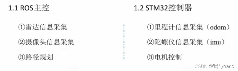
ROS主控采用的Jetson nano B01 STM32主控用的是F407,通过Jetson 驱动雷达采集信息,然后串口像STM32发送相关的运动指令,串口接收到后执行相应的动作。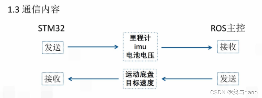
二、硬件连接
硬件连接很简单用的是平衡小车之家的ROS STM32控制板,其内置电平转换芯片,只需用一根USB数据线连接起来即可。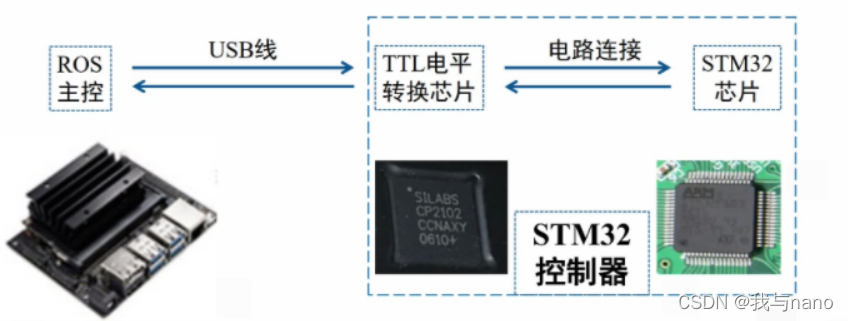
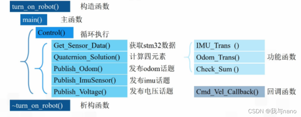
构造函数和析构函数是类的另一种操作,首先获取STM32数据也就是获取陀螺仪数据,然后计算出四元素,将相关信息发送给STM32
turn_on_robot::~turn_on_robot()
{
//Sends the stop motion command to the lower machine before the turn_on_robot object ends
//瀵硅薄turn_on_robot缁撴潫鍓嶅悜涓嬩綅鏈哄彂閫佸仠姝㈣繍鍔ㄥ懡浠?
Send_Data.tx[0]=FRAME_HEADER;
Send_Data.tx[1] = 0;
Send_Data.tx[2] = 0;
//The target velocity of the X-axis of the robot //鏈哄櫒浜篨杞寸殑鐩爣绾块€熷害
Send_Data.tx[4] = 0;
Send_Data.tx[3] = 0;
//The target velocity of the Y-axis of the robot //鏈哄櫒浜篩杞寸殑鐩爣绾块€熷害
Send_Data.tx[6] = 0;
Send_Data.tx[5] = 0;
//The target velocity of the Z-axis of the robot //鏈哄櫒浜篫杞寸殑鐩爣瑙掗€熷害
Send_Data.tx[8] = 0;
Send_Data.tx[7] = 0;
Send_Data.tx[9]=Check_Sum(9,SEND_DATA_CHECK); //Check the bits for the Check_Sum function //鏍¢獙浣嶏紝瑙勫垯鍙傝Check_Sum鍑芥暟
Send_Data.tx[10]=FRAME_TAIL;
try
{
Stm32_Serial.write(Send_Data.tx,sizeof (Send_Data.tx)); //Send data to the serial port //鍚戜覆鍙e彂鏁版嵁
}
catch (serial::IOException& e)
{
ROS_ERROR_STREAM("Unable to send data through serial port"); //If sending data fails, an error message is printed //濡傛灉鍙戦€佹暟鎹け璐?鎵撳嵃閿欒淇℃伅
}
Stm32_Serial.close(); //Close the serial port //鍏抽棴涓插彛
ROS_INFO_STREAM("Shutting down"); //Prompt message //鎻愮ず淇℃伅
}
uart.c
#include "usartx.h"
SEND_DATA Send_Data;
RECEIVE_DATA Receive_Data;
extern int Time_count;
/**************************************************************************
Function: Usartx3, Usartx1 and CAN send data task
Input : none
Output : none
º¯Êý¹¦ÄÜ£º´®¿Ú3¡¢´®¿Ú1¡¢´®¿Ú5¡¢CAN·¢ËÍÊý¾ÝÈÎÎñ
Èë¿Ú²ÎÊý£ºÎÞ
·µ»Ø Öµ£ºÎÞ
**************************************************************************/
void data_task(void *pvParameters)
{
u32 lastWakeTime = getSysTickCnt();
while(1)
{
//The task is run at 20hz
//´ËÈÎÎñÒÔ20HzµÄƵÂÊÔËÐÐ
vTaskDelayUntil(&lastWakeTime, F2T(RATE_20_HZ));
//Assign the data to be sent
//¶ÔÒª½øÐз¢Ë͵ÄÊý¾Ý½øÐи³Öµ
data_transition();
USART1_SEND(); //Serial port 1 sends data //´®¿Ú1·¢ËÍÊý¾Ý
USART3_SEND(); //Serial port 3 (ROS) sends data //´®¿Ú3(ROS)·¢ËÍÊý¾Ý
USART5_SEND(); //Serial port 5 sends data //´®¿Ú5·¢ËÍÊý¾Ý
CAN_SEND(); //CAN send data //CAN·¢ËÍÊý¾Ý
}
}
/**************************************************************************
Function: The data sent by the serial port is assigned
Input : none
Output : none
º¯Êý¹¦ÄÜ£º´®¿Ú·¢Ë͵ÄÊý¾Ý½øÐи³Öµ
Èë¿Ú²ÎÊý£ºÎÞ
·µ»Ø Öµ£ºÎÞ
**************************************************************************/
void data_transition(void)
{
Send_Data.Sensor_Str.Frame_Header = FRAME_HEADER; //Frame_header //Ö¡Í·
Send_Data.Sensor_Str.Frame_Tail = FRAME_TAIL; //Frame_tail //֡β
//According to different vehicle types, different kinematics algorithms were selected to carry out the forward kinematics solution,
//and the three-axis velocity was obtained from each wheel velocity
//¸ù¾Ý²»Í¬³µÐÍÑ¡Ôñ²»Í¬Ô˶¯Ñ§Ëã·¨½øÐÐÔ˶¯Ñ§Õý½â£¬´Ó¸÷³µÂÖËÙ¶ÈÇó³öÈýÖáËÙ¶È
switch(Car_Mode)
{
case Mec_Car:
Send_Data.Sensor_Str.X_speed = ((MOTOR_A.Encoder+MOTOR_B.Encoder+MOTOR_C.Encoder+MOTOR_D.Encoder)/4)*1000;
Send_Data.Sensor_Str.Y_speed = ((MOTOR_A.Encoder-MOTOR_B.Encoder+MOTOR_C.Encoder-MOTOR_D.Encoder)/4)*1000;
Send_Data.Sensor_Str.Z_speed = ((-MOTOR_A.Encoder-MOTOR_B.Encoder+MOTOR_C.Encoder+MOTOR_D.Encoder)/4/(Axle_spacing+Wheel_spacing))*1000;
break;
case Omni_Car:
Send_Data.Sensor_Str.X_speed = ((MOTOR_C.Encoder-MOTOR_B.Encoder)/2/X_PARAMETER)*1000;
Send_Data.Sensor_Str.Y_speed = ((MOTOR_A.Encoder*2-MOTOR_B.Encoder-MOTOR_C.Encoder)/3)*1000;
Send_Data.Sensor_Str.Z_speed = ((MOTOR_A.Encoder+MOTOR_B.Encoder+MOTOR_C.Encoder)/3/Omni_turn_radiaus)*1000;
break;
case Akm_Car:
Send_Data.Sensor_Str.X_speed = ((MOTOR_A.Encoder+MOTOR_B.Encoder)/2)*1000;
Send_Data.Sensor_Str.Y_speed = 0;
Send_Data.Sensor_Str.Z_speed = ((MOTOR_B.Encoder-MOTOR_A.Encoder)/Wheel_spacing)*1000;
break;
case Diff_Car:
Send_Data.Sensor_Str.X_speed = ((MOTOR_A.Encoder+MOTOR_B.Encoder)/2)*1000;
Send_Data.Sensor_Str.Y_speed = 0;
Send_Data.Sensor_Str.Z_speed = ((MOTOR_B.Encoder-MOTOR_A.Encoder)/Wheel_spacing)*1000;
break;
case FourWheel_Car:
Send_Data.Sensor_Str.X_speed = ((MOTOR_A.Encoder+MOTOR_B.Encoder+MOTOR_C.Encoder+MOTOR_D.Encoder)/4)*1000;
Send_Data.Sensor_Str.Y_speed = 0;
Send_Data.Sensor_Str.Z_speed = ((-MOTOR_B.Encoder-MOTOR_A.Encoder+MOTOR_C.Encoder+MOTOR_D.Encoder)/2/(Axle_spacing+Wheel_spacing))*1000;
break;
case Tank_Car:
Send_Data.Sensor_Str.X_speed = ((MOTOR_A.Encoder+MOTOR_B.Encoder)/2)*1000;
Send_Data.Sensor_Str.Y_speed = 0;
Send_Data.Sensor_Str.Z_speed = ((MOTOR_B.Encoder-MOTOR_A.Encoder)/(Wheel_spacing)*1000);
break;
}
//The acceleration of the triaxial acceleration //¼ÓËٶȼÆÈýÖá¼ÓËÙ¶È
Send_Data.Sensor_Str.Accelerometer.X_data= accel[1]; //The accelerometer Y-axis is converted to the ros coordinate X axis //¼ÓËٶȼÆYÖáת»»µ½ROS×ø±êXÖá
Send_Data.Sensor_Str.Accelerometer.Y_data=-accel[0]; //The accelerometer X-axis is converted to the ros coordinate y axis //¼ÓËٶȼÆXÖáת»»µ½ROS×ø±êYÖá
Send_Data.Sensor_Str.Accelerometer.Z_data= accel[2]; //The accelerometer Z-axis is converted to the ros coordinate Z axis //¼ÓËٶȼÆZÖáת»»µ½ROS×ø±êZÖá
//The Angle velocity of the triaxial velocity //½ÇËٶȼÆÈýÖá½ÇËÙ¶È
Send_Data.Sensor_Str.Gyroscope.X_data= gyro[1]; //The Y-axis is converted to the ros coordinate X axis //½ÇËٶȼÆYÖáת»»µ½ROS×ø±êXÖá
Send_Data.Sensor_Str.Gyroscope.Y_data=-gyro[0]; //The X-axis is converted to the ros coordinate y axis //½ÇËٶȼÆXÖáת»»µ½ROS×ø±êYÖá
if(Flag_Stop==0)
//If the motor control bit makes energy state, the z-axis velocity is sent normall
//Èç¹ûµç»ú¿ØÖÆλʹÄÜ״̬£¬ÄÇôÕý³£·¢ËÍZÖá½ÇËÙ¶È
Send_Data.Sensor_Str.Gyroscope.Z_data=gyro[2];
else
//If the robot is static (motor control dislocation), the z-axis is 0
//Èç¹û»úÆ÷ÈËÊǾ²Ö¹µÄ£¨µç»ú¿ØÖÆλʧÄÜ£©£¬ÄÇô·¢Ë͵ÄZÖá½ÇËÙ¶ÈΪ0
Send_Data.Sensor_Str.Gyroscope.Z_data=0;
//Battery voltage (this is a thousand times larger floating point number, which will be reduced by a thousand times as well as receiving the data).
//µç³Øµçѹ(ÕâÀォ¸¡µãÊý·Å´óһǧ±¶´«Ê䣬ÏàÓ¦µÄÔÚ½ÓÊÕ¶ËÔÚ½ÓÊÕµ½Êý¾ÝºóÒ²»áËõСһǧ±¶)
Send_Data.Sensor_Str.Power_Voltage = Voltage*1000;
Send_Data.buffer[0]=Send_Data.Sensor_Str.Frame_Header; //Frame_heade //Ö¡Í·
Send_Data.buffer[1]=Flag_Stop; //Car software loss marker //С³µÈí¼þʧÄܱê־λ
//The three-axis speed of / / car is split into two eight digit Numbers
//С³µÈýÖáËÙ¶È,¸÷Öᶼ²ð·ÖΪÁ½¸ö8λÊý¾ÝÔÙ·¢ËÍ
Send_Data.buffer[2]=Send_Data.Sensor_Str.X_speed >>8;
Send_Data.buffer[3]=Send_Data.Sensor_Str.X_speed ;
Send_Data.buffer[4]=Send_Data.Sensor_Str.Y_speed>>8;
Send_Data.buffer[5]=Send_Data.Sensor_Str.Y_speed;
Send_Data.buffer[6]=Send_Data.Sensor_Str.Z_speed >>8;
Send_Data.buffer[7]=Send_Data.Sensor_Str.Z_speed ;
//The acceleration of the triaxial axis of / / imu accelerometer is divided into two eight digit reams
//IMU¼ÓËٶȼÆÈýÖá¼ÓËÙ¶È,¸÷Öᶼ²ð·ÖΪÁ½¸ö8λÊý¾ÝÔÙ·¢ËÍ
Send_Data.buffer[8]=Send_Data.Sensor_Str.Accelerometer.X_data>>8;
Send_Data.buffer[9]=Send_Data.Sensor_Str.Accelerometer.X_data;
Send_Data.buffer[10]=Send_Data.Sensor_Str.Accelerometer.Y_data>>8;
Send_Data.buffer[11]=Send_Data.Sensor_Str.Accelerometer.Y_data;
Send_Data.buffer[12]=Send_Data.Sensor_Str.Accelerometer.Z_data>>8;
Send_Data.buffer[13]=Send_Data.Sensor_Str.Accelerometer.Z_data;
//The axis of the triaxial velocity of the / /imu is divided into two eight digits
//IMU½ÇËٶȼÆÈýÖá½ÇËÙ¶È,¸÷Öᶼ²ð·ÖΪÁ½¸ö8λÊý¾ÝÔÙ·¢ËÍ
Send_Data.buffer[14]=Send_Data.Sensor_Str.Gyroscope.X_data>>8;
Send_Data.buffer[15]=Send_Data.Sensor_Str.Gyroscope.X_data;
Send_Data.buffer[16]=Send_Data.Sensor_Str.Gyroscope.Y_data>>8;
Send_Data.buffer[17]=Send_Data.Sensor_Str.Gyroscope.Y_data;
Send_Data.buffer[18]=Send_Data.Sensor_Str.Gyroscope.Z_data>>8;
Send_Data.buffer[19]=Send_Data.Sensor_Str.Gyroscope.Z_data;
//Battery voltage, split into two 8 digit Numbers
//µç³Øµçѹ,²ð·ÖΪÁ½¸ö8λÊý¾Ý·¢ËÍ
Send_Data.buffer[20]=Send_Data.Sensor_Str.Power_Voltage >>8;
Send_Data.buffer[21]=Send_Data.Sensor_Str.Power_Voltage;
//Data check digit calculation, Pattern 1 is a data check
//Êý¾ÝУÑéλ¼ÆË㣬ģʽ1ÊÇ·¢ËÍÊý¾ÝУÑé
Send_Data.buffer[22]=Check_Sum(22,1);
Send_Data.buffer[23]=Send_Data.Sensor_Str.Frame_Tail; //Frame_tail //֡β
}
/**************************************************************************
Function: Serial port 1 sends data
Input : none
Output : none
º¯Êý¹¦ÄÜ£º´®¿Ú1·¢ËÍÊý¾Ý
Èë¿Ú²ÎÊý£ºÎÞ
·µ»Ø Öµ£ºÎÞ
**************************************************************************/
void USART1_SEND(void)
{
unsigned char i = 0;
for(i=0; i<24; i++)
{
usart1_send(Send_Data.buffer[i]);
}
}
/**************************************************************************
Function: Serial port 3 sends data
Input : none
Output : none
º¯Êý¹¦ÄÜ£º´®¿Ú3·¢ËÍÊý¾Ý
Èë¿Ú²ÎÊý£ºÎÞ
·µ»Ø Öµ£ºÎÞ
**************************************************************************/
void USART3_SEND(void)
{
unsigned char i = 0;
for(i=0; i<24; i++)
{
usart3_send(Send_Data.buffer[i]);
}
}
/**************************************************************************
Function: Serial port 5 sends data
Input : none
Output : none
º¯Êý¹¦ÄÜ£º´®¿Ú5·¢ËÍÊý¾Ý
Èë¿Ú²ÎÊý£ºÎÞ
·µ»Ø Öµ£ºÎÞ
**************************************************************************/
void USART5_SEND(void)
{
unsigned char i = 0;
for(i=0; i<24; i++)
{
usart5_send(Send_Data.buffer[i]);
}
}
/**************************************************************************
Function: CAN sends data
Input : none
Output : none
º¯Êý¹¦ÄÜ£ºCAN·¢ËÍÊý¾Ý
Èë¿Ú²ÎÊý£ºÎÞ
·µ »Ø Öµ£ºÎÞ
**************************************************************************/
void CAN_SEND(void)
{
u8 CAN_SENT[8],i;
for(i=0;i<8;i++)
{
CAN_SENT[i]=Send_Data.buffer[i];
}
CAN1_Send_Num(0x101,CAN_SENT);
for(i=0;i<8;i++)
{
CAN_SENT[i]=Send_Data.buffer[i+8];
}
CAN1_Send_Num(0x102,CAN_SENT);
for(i=0;i<8;i++)
{
CAN_SENT[i]=Send_Data.buffer[i+16];
}
CAN1_Send_Num(0x103,CAN_SENT);
}
/**************************************************************************
Function: Serial port 1 initialization
Input : none
Output : none
º¯Êý¹¦ÄÜ£º´®¿Ú1³õʼ»¯
Èë¿Ú²ÎÊý£ºÎÞ
·µ »Ø Öµ£ºÎÞ
**************************************************************************/
void uart1_init(u32 bound)
{
GPIO_InitTypeDef GPIO_InitStructure;
USART_InitTypeDef USART_InitStructure;
NVIC_InitTypeDef NVIC_InitStructure;
RCC_APB2PeriphClockCmd(RCC_APB2Periph_GPIOA, ENABLE); //Enable the gpio clock //ʹÄÜGPIOʱÖÓ
RCC_APB2PeriphClockCmd(RCC_APB2Periph_USART1, ENABLE); //Enable the Usart clock //ʹÄÜUSARTʱÖÓ
//USART_TX
GPIO_InitStructure.GPIO_Pin = GPIO_Pin_9; //PA9
GPIO_InitStructure.GPIO_Speed = GPIO_Speed_50MHz;
GPIO_InitStructure.GPIO_Mode = GPIO_Mode_AF_PP; //Reuse push-pull output //¸´ÓÃÍÆÍìÊä³ö
GPIO_Init(GPIOA, &GPIO_InitStructure);
//USART_RX
GPIO_InitStructure.GPIO_Pin = GPIO_Pin_10;//PA10
GPIO_InitStructure.GPIO_Mode = GPIO_Mode_IPU; //Float input //¸¡¿ÕÊäÈë
GPIO_Init(GPIOA, &GPIO_InitStructure);
//UsartNVIC configuration //UsartNVICÅäÖÃ
NVIC_InitStructure.NVIC_IRQChannel = USART1_IRQn;
//Preempt priority //ÇÀÕ¼ÓÅÏȼ¶
NVIC_InitStructure.NVIC_IRQChannelPreemptionPriority=1 ;
//Subpriority //×ÓÓÅÏȼ¶
NVIC_InitStructure.NVIC_IRQChannelSubPriority = 0;
//Enable the IRQ channel //IRQͨµÀʹÄÜ
NVIC_InitStructure.NVIC_IRQChannelCmd = ENABLE;
//Initialize the VIC register with the specified parameters
//¸ù¾ÝÖ¸¶¨µÄ²ÎÊý³õʼ»¯VIC¼Ä´æÆ÷
NVIC_Init(&NVIC_InitStructure);
//USART Initialization Settings ³õʼ»¯ÉèÖÃ
USART_InitStructure.USART_BaudRate = bound; //Port rate //´®¿Ú²¨ÌØÂÊ
USART_InitStructure.USART_WordLength = USART_WordLength_8b; //The word length is 8 bit data format //×Ö³¤Îª8λÊý¾Ý¸ñʽ
USART_InitStructure.USART_StopBits = USART_StopBits_1; //A stop bit //Ò»¸öֹͣλ
USART_InitStructure.USART_Parity = USART_Parity_No; //Prosaic parity bits //ÎÞÆæżУÑéλ
USART_InitStructure.USART_HardwareFlowControl = USART_HardwareFlowControl_None; //No hardware data flow control //ÎÞÓ²¼þÊý¾ÝÁ÷¿ØÖÆ
USART_InitStructure.USART_Mode = USART_Mode_Rx | USART_Mode_Tx; //Sending and receiving mode //ÊÕ·¢Ä£Ê½
USART_Init(USART1, &USART_InitStructure); //Initialize serial port 1 //³õʼ»¯´®¿Ú1
USART_ITConfig(USART1, USART_IT_RXNE, ENABLE); //Open the serial port to accept interrupts //¿ªÆô´®¿Ú½ÓÊÜÖжÏ
USART_Cmd(USART1, ENABLE); //Enable serial port 1 //ʹÄÜ´®¿Ú1
}
/**************************************************************************
Function: Serial port 2 initialization
Input : none
Output : none
º¯Êý¹¦ÄÜ£º´®¿Ú2³õʼ»¯
Èë¿Ú²ÎÊý£ºÎÞ
·µ»Ø Öµ£ºÎÞ
**************************************************************************/
void uart2_init(u32 bound)
{
GPIO_InitTypeDef GPIO_InitStructure;
USART_InitTypeDef USART_InitStructure;
NVIC_InitTypeDef NVIC_InitStructure;
RCC_APB2PeriphClockCmd(RCC_APB2Periph_AFIO,ENABLE); //Enable the AFIO clock //ʹÄÜAFIOʱÖÓ
RCC_APB2PeriphClockCmd(RCC_APB2Periph_GPIOD, ENABLE); //Enable the gpio clock //ʹÄÜGPIOʱÖÓ
RCC_APB1PeriphClockCmd(RCC_APB1Periph_USART2, ENABLE); //Enable the Usart clock //ʹÄÜUSARTʱÖÓ
GPIO_PinRemapConfig(GPIO_Remap_USART2, ENABLE); //Pin remapping //Òý½ÅÖØÓ³Éä
//USART_TX
GPIO_InitStructure.GPIO_Pin = GPIO_Pin_5; //PD5
GPIO_InitStructure.GPIO_Speed = GPIO_Speed_50MHz;
GPIO_InitStructure.GPIO_Mode = GPIO_Mode_AF_PP; //Reuse push-pull output //¸´ÓÃÍÆÍìÊä³ö
GPIO_Init(GPIOD, &GPIO_InitStructure);
//USART_RX
GPIO_InitStructure.GPIO_Pin = GPIO_Pin_6; //PD6
GPIO_InitStructure.GPIO_Mode = GPIO_Mode_IPU; //Pull up input//ÉÏÀÊäÈë
GPIO_Init(GPIOD, &GPIO_InitStructure);
//UsartNVIC configuration //UsartNVICÅäÖÃ
NVIC_InitStructure.NVIC_IRQChannel = USART2_IRQn;
//Preempt priority //ÇÀÕ¼ÓÅÏȼ¶
NVIC_InitStructure.NVIC_IRQChannelPreemptionPriority=1 ;
//Subpriority //×ÓÓÅÏȼ¶
NVIC_InitStructure.NVIC_IRQChannelSubPriority = 0;
//Enable the IRQ channel //IRQͨµÀʹÄÜ
NVIC_InitStructure.NVIC_IRQChannelCmd = ENABLE;
//Initialize the VIC register with the specified parameters
//¸ù¾ÝÖ¸¶¨µÄ²ÎÊý³õʼ»¯VIC¼Ä´æÆ÷
NVIC_Init(&NVIC_InitStructure);
//USART Initialization Settings ³õʼ»¯ÉèÖÃ
USART_InitStructure.USART_BaudRate = bound; //Port rate //´®¿Ú²¨ÌØÂÊ
USART_InitStructure.USART_WordLength = USART_WordLength_8b; //The word length is 8 bit data format //×Ö³¤Îª8λÊý¾Ý¸ñʽ
USART_InitStructure.USART_StopBits = USART_StopBits_1; //A stop bit //Ò»¸öÍ£Ö¹
USART_InitStructure.USART_Parity = USART_Parity_No; //Prosaic parity bits //ÎÞÆæżУÑéλ
USART_InitStructure.USART_HardwareFlowControl = USART_HardwareFlowControl_None; //No hardware data flow control //ÎÞÓ²¼þÊý¾ÝÁ÷¿ØÖÆ
USART_InitStructure.USART_Mode = USART_Mode_Rx | USART_Mode_Tx; //Sending and receiving mode //ÊÕ·¢Ä£Ê½
USART_Init(USART2, &USART_InitStructure); //Initialize serial port 2 //³õʼ»¯´®¿Ú2
USART_ITConfig(USART2, USART_IT_RXNE, ENABLE); //Open the serial port to accept interrupts //¿ªÆô´®¿Ú½ÓÊÜÖжÏ
USART_Cmd(USART2, ENABLE); //Enable serial port 2 //ʹÄÜ´®¿Ú2
}
/**************************************************************************
Function: Serial port 3 initialization
Input : none
Output : none
º¯Êý¹¦ÄÜ£º´®¿Ú3³õʼ»¯
Èë¿Ú²ÎÊý£ºÎÞ
·µ»Ø Öµ£ºÎÞ
**************************************************************************/
void uart3_init(u32 bound)
{
GPIO_InitTypeDef GPIO_InitStructure;
USART_InitTypeDef USART_InitStructure;
NVIC_InitTypeDef NVIC_InitStructure;
RCC_APB2PeriphClockCmd(RCC_APB2Periph_AFIO,ENABLE); //Enable the AFIO clock //ʹÄÜAFIOʱÖÓ
RCC_APB2PeriphClockCmd(RCC_APB2Periph_GPIOC, ENABLE); //Enable the gpio clock //ʹÄÜGPIOʱÖÓ
RCC_APB1PeriphClockCmd(RCC_APB1Periph_USART3, ENABLE); //Enable the Usart clock //ʹÄÜUSARTʱÖÓ
GPIO_PinRemapConfig(GPIO_PartialRemap_USART3, ENABLE); //Pin remapping //Òý½ÅÖØÓ³Éä
//USART_TX
GPIO_InitStructure.GPIO_Pin = GPIO_Pin_10; //C10
GPIO_InitStructure.GPIO_Speed = GPIO_Speed_50MHz;
GPIO_InitStructure.GPIO_Mode = GPIO_Mode_AF_PP; //Reuse push-pull output //¸´ÓÃÍÆÍìÊä³ö
GPIO_Init(GPIOC, &GPIO_InitStructure);
//USART_RX
GPIO_InitStructure.GPIO_Pin = GPIO_Pin_11; //PC11
GPIO_InitStructure.GPIO_Mode = GPIO_Mode_IPU; //Pull up input//ÉÏÀÊäÈë
GPIO_Init(GPIOC, &GPIO_InitStructure);
//UsartNVIC configuration //UsartNVICÅäÖÃ
NVIC_InitStructure.NVIC_IRQChannel = USART3_IRQn;
//Preempt priority //ÇÀÕ¼ÓÅÏȼ¶
NVIC_InitStructure.NVIC_IRQChannelPreemptionPriority=2 ;
//Preempt priority //ÇÀÕ¼ÓÅÏȼ¶
NVIC_InitStructure.NVIC_IRQChannelSubPriority = 0;
//Enable the IRQ channel //IRQͨµÀʹÄÜ
NVIC_InitStructure.NVIC_IRQChannelCmd = ENABLE;
//Initialize the VIC register with the specified parameters
//¸ù¾ÝÖ¸¶¨µÄ²ÎÊý³õʼ»¯VIC¼Ä´æÆ÷
NVIC_Init(&NVIC_InitStructure);
//USART Initialization Settings ³õʼ»¯ÉèÖÃ
USART_InitStructure.USART_BaudRate = bound; //Port rate //´®¿Ú²¨ÌØÂÊ
USART_InitStructure.USART_WordLength = USART_WordLength_8b; //The word length is 8 bit data format //×Ö³¤Îª8λÊý¾Ý¸ñʽ
USART_InitStructure.USART_StopBits = USART_StopBits_1; //A stop bit //Ò»¸öÍ£Ö¹
USART_InitStructure.USART_Parity = USART_Parity_No; //Prosaic parity bits //ÎÞÆæżУÑéλ
USART_InitStructure.USART_HardwareFlowControl = USART_HardwareFlowControl_None; //No hardware data flow control //ÎÞÓ²¼þÊý¾ÝÁ÷¿ØÖÆ
USART_InitStructure.USART_Mode = USART_Mode_Rx | USART_Mode_Tx; //Sending and receiving mode //ÊÕ·¢Ä£Ê½
USART_Init(USART3, &USART_InitStructure); //Initialize serial port 3 //³õʼ»¯´®¿Ú3
USART_ITConfig(USART3, USART_IT_RXNE, ENABLE); //Open the serial port to accept interrupts //¿ªÆô´®¿Ú½ÓÊÜÖжÏ
USART_Cmd(USART3, ENABLE); //Enable serial port 3 //ʹÄÜ´®¿Ú3
}
/**************************************************************************
Function: Serial port 5 initialization
Input : none
Output : none
º¯Êý¹¦ÄÜ£º´®¿Ú5³õʼ»¯
Èë¿Ú²ÎÊý£ºÎÞ
·µ»Ø Öµ£ºÎÞ
**************************************************************************/
void uart5_init(u32 bound)
{
GPIO_InitTypeDef GPIO_InitStructure;
USART_InitTypeDef USART_InitStructure;
NVIC_InitTypeDef NVIC_InitStructure;
RCC_APB2PeriphClockCmd(RCC_APB2Periph_AFIO,ENABLE); //Enable the AFIO clock //ʹÄÜAFIOʱÖÓ
RCC_APB2PeriphClockCmd(RCC_APB2Periph_GPIOC, ENABLE); //Enable the gpio clock //ʹÄÜGPIOʱÖÓ
RCC_APB1PeriphClockCmd(RCC_APB1Periph_UART5, ENABLE); //Enable the Usart clock //ʹÄÜUSARTʱÖÓ
//USART_TX
GPIO_InitStructure.GPIO_Pin = GPIO_Pin_12; //C12
GPIO_InitStructure.GPIO_Speed = GPIO_Speed_50MHz;
GPIO_InitStructure.GPIO_Mode = GPIO_Mode_AF_PP; //Reuse push-pull output //¸´ÓÃÍÆÍìÊä³ö
GPIO_Init(GPIOC, &GPIO_InitStructure);
//USART_RX
GPIO_InitStructure.GPIO_Pin = GPIO_Pin_2; //PD2
GPIO_InitStructure.GPIO_Mode = GPIO_Mode_IPU; //Pull up input//ÉÏÀÊäÈë
GPIO_Init(GPIOD, &GPIO_InitStructure);
//UsartNVIC configuration //UsartNVICÅäÖÃ
NVIC_InitStructure.NVIC_IRQChannel = UART5_IRQn;
//Preempt priority //ÇÀÕ¼ÓÅÏȼ¶
NVIC_InitStructure.NVIC_IRQChannelPreemptionPriority=2 ;
//Preempt priority //ÇÀÕ¼ÓÅÏȼ¶
NVIC_InitStructure.NVIC_IRQChannelSubPriority = 0;
//Enable the IRQ channel //IRQͨµÀʹÄÜ
NVIC_InitStructure.NVIC_IRQChannelCmd = ENABLE;
//Initialize the VIC register with the specified parameters
//¸ù¾ÝÖ¸¶¨µÄ²ÎÊý³õʼ»¯VIC¼Ä´æÆ÷
NVIC_Init(&NVIC_InitStructure);
//USART Initialization Settings ³õʼ»¯ÉèÖÃ
USART_InitStructure.USART_BaudRate = bound; //Port rate //´®¿Ú²¨ÌØÂÊ
USART_InitStructure.USART_WordLength = USART_WordLength_8b; //The word length is 8 bit data format //×Ö³¤Îª8λÊý¾Ý¸ñʽ
USART_InitStructure.USART_StopBits = USART_StopBits_1; //A stop bit //Ò»¸öÍ£Ö¹
USART_InitStructure.USART_Parity = USART_Parity_No; //Prosaic parity bits //ÎÞÆæżУÑéλ
USART_InitStructure.USART_HardwareFlowControl = USART_HardwareFlowControl_None; //No hardware data flow control //ÎÞÓ²¼þÊý¾ÝÁ÷¿ØÖÆ
USART_InitStructure.USART_Mode = USART_Mode_Rx | USART_Mode_Tx; //Sending and receiving mode //ÊÕ·¢Ä£Ê½
USART_Init(UART5, &USART_InitStructure); //Initialize serial port 5 //³õʼ»¯´®¿Ú5
USART_ITConfig(UART5, USART_IT_RXNE, ENABLE); //Open the serial port to accept interrupts //¿ªÆô´®¿Ú½ÓÊÜÖжÏ
USART_Cmd(UART5, ENABLE); //Enable serial port 5 //ʹÄÜ´®¿Ú5
}
/**************************************************************************
Function: Serial port 1 receives interrupted
Input : none
Output : none
º¯Êý¹¦ÄÜ£º´®¿Ú1½ÓÊÕÖжÏ
Èë¿Ú²ÎÊý£ºÎÞ
·µ »Ø Öµ£ºÎÞ
**************************************************************************/
int USART1_IRQHandler(void)
{
if(USART_GetITStatus(USART1, USART_IT_RXNE) != RESET) //Check if data is received //ÅжÏÊÇ·ñ½ÓÊÕµ½Êý¾Ý
{
u8 Usart_Receive;
static u8 Count;
static u8 rxbuf[11];
int check=0,error=1,i;
Usart_Receive = USART_ReceiveData(USART1); //Read the data //¶ÁÈ¡Êý¾Ý
if(Time_count<CONTROL_DELAY)
// Data is not processed until 10 seconds after startup
//¿ª»ú10ÃëÇ°²»´¦ÀíÊý¾Ý
return 0;
//Fill the array with serial data
//´®¿ÚÊý¾ÝÌîÈëÊý×é
rxbuf[Count]=Usart_Receive;
//Ensure that the first data in the array is FRAME_HEADER
//È·±£Êý×éµÚÒ»¸öÊý¾ÝΪFRAME_HEADER
if(Usart_Receive == FRAME_HEADER||Count>0)
Count++;
else
Count=0;
if (Count == 11) //Verify the length of the packet //ÑéÖ¤Êý¾Ý°üµÄ³¤¶È
{
Count=0; //Prepare for the serial port data to be refill into the array //Ϊ´®¿ÚÊý¾ÝÖØÐÂÌîÈëÊý×é×ö×¼±¸
if(rxbuf[10] == FRAME_TAIL) //Verify the frame tail of the packet //ÑéÖ¤Êý¾Ý°üµÄ֡β
{
for(i=0; i<9; i++)
{
//XOR bit check, used to detect data error
//Òì»òλУÑ飬ÓÃÓÚ¼ì²âÊý¾ÝÊÇ·ñ³ö´í
check=rxbuf[i]^check;
}
if(check==rxbuf[9])
//XOR bit check successful
//Òì»òλУÑé³É¹¦
error=0;
if(error==0)
{
float Vz;
if(Usart1_ON_Flag==0)
{
//Serial port 1 controls flag position 1, other flag position 0
//´®¿Ú1¿ØÖƱê־λÖÃ1£¬ÆäËü±ê־λÖÃ0
Usart1_ON_Flag=1;
Usart5_ON_Flag=0;
APP_ON_Flag=0;
PS2_ON_Flag=0;
Remote_ON_Flag=0;
CAN_ON_Flag=0;
}
//Calculate the 3-axis target velocity from the serial data, which is divided into 8-bit high and 8-bit low units m/s
//´Ó´®¿ÚÊý¾ÝÇóÈýÖáÄ¿±êËٶȣ¬·Ö¸ß8λºÍµÍ8λ µ¥Î»m/s
Move_X=XYZ_Target_Speed_transition(rxbuf[3],rxbuf[4]);
Move_Y=XYZ_Target_Speed_transition(rxbuf[5],rxbuf[6]);
Vz =XYZ_Target_Speed_transition(rxbuf[7],rxbuf[8]);
if(Car_Mode==Akm_Car)
{
Move_Z=Vz_to_Akm_Angle(Move_X, Vz);
}
else
{
Move_Z=XYZ_Target_Speed_transition(rxbuf[7],rxbuf[8]);
}
}
}
}
}
return 0;
}
/**************************************************************************
Function: Refresh the OLED screen
Input : none
Output : none
º¯Êý¹¦ÄÜ£º´®¿Ú2½ÓÊÕÖжÏ
Èë¿Ú²ÎÊý£ºÎÞ
·µ»Ø Öµ£ºÎÞ
**************************************************************************/
int USART2_IRQHandler(void)
{
int Usart_Receive;
if(USART_GetITStatus(USART2, USART_IT_RXNE) != RESET) //Check if data is received //ÅжÏÊÇ·ñ½ÓÊÕµ½Êý¾Ý
{
static u8 Flag_PID,i,j,Receive[50],Last_Usart_Receive;
static float Data;
Usart_Receive=USART2->DR; //Read the data //¶ÁÈ¡Êý¾Ý
if(Deviation_Count<CONTROL_DELAY)
// Data is not processed until 10 seconds after startup
//¿ª»ú10ÃëÇ°²»´¦ÀíÊý¾Ý
return 0;
if(Usart_Receive==0x41&&Last_Usart_Receive==0x41&&APP_ON_Flag==0)
//10 seconds after startup, press the forward button of APP to enter APP control mode
//The APP controls the flag position 1 and the other flag position 0
//¿ª»ú10ÃëÖ®ºó£¬°´ÏÂAPPµÄÇ°½ø¼ü½øÈëAPP¿ØÖÆģʽ
//APP¿ØÖƱê־λÖÃ1£¬ÆäËü±ê־λÖÃ0
PS2_ON_Flag=0,Remote_ON_Flag=0,APP_ON_Flag=1,CAN_ON_Flag=0,Usart1_ON_Flag=0, Usart5_ON_Flag=0;
Last_Usart_Receive=Usart_Receive;
if(Usart_Receive==0x4B)
//Enter the APP steering control interface
//½øÈëAPPתÏò¿ØÖƽçÃæ
Turn_Flag=1;
else if(Usart_Receive==0x49||Usart_Receive==0x4A)
// Enter the APP direction control interface
//½øÈëAPP·½Ïò¿ØÖƽçÃæ
Turn_Flag=0;
if(Turn_Flag==0)
{
//App rocker control interface command
//APPÒ¡¸Ë¿ØÖƽçÃæÃüÁî
if(Usart_Receive>=0x41&&Usart_Receive<=0x48)
{
Flag_Direction=Usart_Receive-0x40;
}
else if(Usart_Receive<=8)
{
Flag_Direction=Usart_Receive;
}
else Flag_Direction=0;
}
else if(Turn_Flag==1)
{
//APP steering control interface command
//APPתÏò¿ØÖƽçÃæÃüÁî
if (Usart_Receive==0x43) Flag_Left=0,Flag_Right=1; //Right rotation //ÓÒ×Ôת
else if(Usart_Receive==0x47) Flag_Left=1,Flag_Right=0; //Left rotation //×ó×Ôת
else Flag_Left=0,Flag_Right=0;
if (Usart_Receive==0x41||Usart_Receive==0x45) Flag_Direction=Usart_Receive-0x40;
else Flag_Direction=0;
}
if(Usart_Receive==0x58) RC_Velocity=RC_Velocity+100; //Accelerate the keys, +100mm/s //¼ÓËÙ°´¼ü£¬+100mm/s
if(Usart_Receive==0x59) RC_Velocity=RC_Velocity-100; //Slow down buttons, -100mm/s //¼õËÙ°´¼ü£¬-100mm/s
// The following is the communication with the APP debugging interface
//ÒÔÏÂÊÇÓëAPPµ÷ÊÔ½çÃæͨѶ
if(Usart_Receive==0x7B) Flag_PID=1; //The start bit of the APP parameter instruction //APP²ÎÊýÖ¸ÁîÆðʼλ
if(Usart_Receive==0x7D) Flag_PID=2; //The APP parameter instruction stops the bit //APP²ÎÊýÖ¸Áîֹͣλ
if(Flag_PID==1) //Collect data //²É¼¯Êý¾Ý
{
Receive[i]=Usart_Receive;
i++;
}
if(Flag_PID==2) //Analyze the data //·ÖÎöÊý¾Ý
{
if(Receive[3]==0x50) PID_Send=1;
else if(Receive[1]!=0x23)
{
for(j=i;j>=4;j--)
{
Data+=(Receive[j-1]-48)*pow(10,i-j);
}
switch(Receive[1])
{
case 0x30: RC_Velocity=Data;break;
case 0x31: Velocity_KP=Data;break;
case 0x32: Velocity_KI=Data;break;
case 0x33: break;
case 0x34: break;
case 0x35: break;
case 0x36: break;
case 0x37: break;
case 0x38: break;
}
}
//Relevant flag position is cleared
//Ïà¹Ø±ê־λÇåÁã
Flag_PID=0;
i=0;
j=0;
Data=0;
memset(Receive, 0, sizeof(u8)*50); //Clear the array to zero//Êý×éÇåÁã
}
if(RC_Velocity<0) RC_Velocity=0;
}
return 0;
}
/**************************************************************************
Function: Serial port 3 receives interrupted
Input : none
Output : none
º¯Êý¹¦ÄÜ£º´®¿Ú3½ÓÊÕÖжÏ
Èë¿Ú²ÎÊý£ºÎÞ
·µ»Ø Öµ£ºÎÞ
**************************************************************************/
int USART3_IRQHandler(void)
{
static u8 Count=0;
u8 Usart_Receive;
if(USART_GetITStatus(USART3, USART_IT_RXNE) != RESET) //Check if data is received //ÅжÏÊÇ·ñ½ÓÊÕµ½Êý¾Ý
{
Usart_Receive = USART_ReceiveData(USART3);//Read the data //¶ÁÈ¡Êý¾Ý
if(Time_count<CONTROL_DELAY)
// Data is not processed until 10 seconds after startup
//¿ª»ú10ÃëÇ°²»´¦ÀíÊý¾Ý
return 0;
//Fill the array with serial data
//´®¿ÚÊý¾ÝÌîÈëÊý×é
Receive_Data.buffer[Count]=Usart_Receive;
// Ensure that the first data in the array is FRAME_HEADER
//È·±£Êý×éµÚÒ»¸öÊý¾ÝΪFRAME_HEADER
if(Usart_Receive == FRAME_HEADER||Count>0)
Count++;
else
Count=0;
if (Count == 11) //Verify the length of the packet //ÑéÖ¤Êý¾Ý°üµÄ³¤¶È
{
Count=0; //Prepare for the serial port data to be refill into the array //Ϊ´®¿ÚÊý¾ÝÖØÐÂÌîÈëÊý×é×ö×¼±¸
if(Receive_Data.buffer[10] == FRAME_TAIL) //Verify the frame tail of the packet //ÑéÖ¤Êý¾Ý°üµÄ֡β
{
//Data exclusionary or bit check calculation, mode 0 is sent data check
//Êý¾ÝÒì»òλУÑé¼ÆË㣬ģʽ0ÊÇ·¢ËÍÊý¾ÝУÑé
if(Receive_Data.buffer[9] ==Check_Sum(9,0))
{
float Vz;
//All modes flag position 0, USART3 control mode
//ËùÓÐģʽ±ê־λÖÃ0£¬ÎªUsart3¿ØÖÆģʽ
PS2_ON_Flag=0;
Remote_ON_Flag=0;
APP_ON_Flag=0;
CAN_ON_Flag=0;
Usart5_ON_Flag=0;
Usart1_ON_Flag=0;
//Calculate the target speed of three axis from serial data, unit m/s
//´Ó´®¿ÚÊý¾ÝÇóÈýÖáÄ¿±êËٶȣ¬ µ¥Î»m/s
Move_X=XYZ_Target_Speed_transition(Receive_Data.buffer[3],Receive_Data.buffer[4]);
Move_Y=XYZ_Target_Speed_transition(Receive_Data.buffer[5],Receive_Data.buffer[6]);
Vz =XYZ_Target_Speed_transition(Receive_Data.buffer[7],Receive_Data.buffer[8]);
if(Car_Mode==Akm_Car)
{
Move_Z=Vz_to_Akm_Angle(Move_X, Vz);
}
else
{
Move_Z=XYZ_Target_Speed_transition(Receive_Data.buffer[7],Receive_Data.buffer[8]);
}
}
}
}
}
return 0;
}
/**************************************************************************
Function: Serial port 5 receives interrupted
Input : none
Output : none
º¯Êý¹¦ÄÜ£º´®¿Ú5½ÓÊÕÖжÏ
Èë¿Ú²ÎÊý£ºÎÞ
·µ»Ø Öµ£ºÎÞ
**************************************************************************/
int UART5_IRQHandler(void)
{
static u8 Count=0;
u8 Usart_Receive;
if(USART_GetITStatus(UART5, USART_IT_RXNE) != RESET) //Check if data is received //ÅжÏÊÇ·ñ½ÓÊÕµ½Êý¾Ý
{
Usart_Receive = USART_ReceiveData(UART5);//Read the data //¶ÁÈ¡Êý¾Ý
if(Time_count<CONTROL_DELAY)
// Data is not processed until 10 seconds after startup
//¿ª»ú10ÃëÇ°²»´¦ÀíÊý¾Ý
return 0;
//Fill the array with serial data
//´®¿ÚÊý¾ÝÌîÈëÊý×é
Receive_Data.buffer[Count]=Usart_Receive;
// Ensure that the first data in the array is FRAME_HEADER
//È·±£Êý×éµÚÒ»¸öÊý¾ÝΪFRAME_HEADER
if(Usart_Receive == FRAME_HEADER||Count>0)
Count++;
else
Count=0;
if (Count == 11) //Verify the length of the packet //ÑéÖ¤Êý¾Ý°üµÄ³¤¶È
{
Count=0; //Prepare for the serial port data to be refill into the array //Ϊ´®¿ÚÊý¾ÝÖØÐÂÌîÈëÊý×é×ö×¼±¸
if(Receive_Data.buffer[10] == FRAME_TAIL) //Verify the frame tail of the packet //ÑéÖ¤Êý¾Ý°üµÄ֡β
{
//Data exclusionary or bit check calculation, mode 0 is sent data check
//Êý¾ÝÒì»òλУÑé¼ÆË㣬ģʽ0ÊÇ·¢ËÍÊý¾ÝУÑé
if(Receive_Data.buffer[9] ==Check_Sum(9,0))
{
float Vz;
//All modes flag position 0, USART5 control mode
//ËùÓÐģʽ±ê־λÖÃ0£¬ÎªUsart5¿ØÖÆģʽ
PS2_ON_Flag=0;
Remote_ON_Flag=0;
APP_ON_Flag=0;
CAN_ON_Flag=0;
Usart5_ON_Flag=1;
Usart1_ON_Flag=0;
//Calculate the target speed of three axis from serial data, unit m/s
//´Ó´®¿ÚÊý¾ÝÇóÈýÖáÄ¿±êËٶȣ¬ µ¥Î»m/s
Move_X=XYZ_Target_Speed_transition(Receive_Data.buffer[3],Receive_Data.buffer[4]);
Move_Y=XYZ_Target_Speed_transition(Receive_Data.buffer[5],Receive_Data.buffer[6]);
Vz =XYZ_Target_Speed_transition(Receive_Data.buffer[7],Receive_Data.buffer[8]);
if(Car_Mode==Akm_Car)
{
Move_Z=Vz_to_Akm_Angle(Move_X, Vz);
}
else
{
Move_Z=XYZ_Target_Speed_transition(Receive_Data.buffer[7],Receive_Data.buffer[8]);
}
}
}
}
}
return 0;
}
/**************************************************************************
Function: After the top 8 and low 8 figures are integrated into a short type data, the unit reduction is converted
Input : 8 bits high, 8 bits low
Output : The target velocity of the robot on the X/Y/Z axis
º¯Êý¹¦ÄÜ£º½«ÉÏλ»ú·¢¹ýÀ´Ä¿±êÇ°½øËÙ¶ÈVx¡¢Ä¿±ê½ÇËÙ¶ÈVz£¬×ª»»Îª°¢¿ËÂüС³µµÄÓÒÇ°ÂÖת½Ç
Èë¿Ú²ÎÊý£ºÄ¿±êÇ°½øËÙ¶ÈVx¡¢Ä¿±ê½ÇËÙ¶ÈVz£¬µ¥Î»£ºm/s£¬rad/s
·µ»Ø Öµ£º°¢¿ËÂüС³µµÄÓÒÇ°ÂÖת½Ç£¬µ¥Î»£ºrad
**************************************************************************/
float Vz_to_Akm_Angle(float Vx, float Vz)
{
float R, AngleR, Min_Turn_Radius;
//float AngleL;
//Ackermann car needs to set minimum turning radius
//If the target speed requires a turn radius less than the minimum turn radius,
//This will greatly improve the friction force of the car, which will seriously affect the control effect
//°¢¿ËÂüС³µÐèÒªÉèÖÃ×îСתÍä°ë¾¶
//Èç¹ûÄ¿±êËÙ¶ÈÒªÇóµÄתÍä°ë¾¶Ð¡ÓÚ×îСתÍä°ë¾¶£¬
//»áµ¼ÖÂС³µÔ˶¯Ä¦²ÁÁ¦´ó´óÌá¸ß£¬ÑÏÖØÓ°Ïì¿ØÖÆЧ¹û
Min_Turn_Radius=MINI_AKM_MIN_TURN_RADIUS;
if(Vz!=0 && Vx!=0)
{
//If the target speed requires a turn radius less than the minimum turn radius
//Èç¹ûÄ¿±êËÙ¶ÈÒªÇóµÄתÍä°ë¾¶Ð¡ÓÚ×îСתÍä°ë¾¶
if(float_abs(Vx/Vz)<=Min_Turn_Radius)
{
//Reduce the target angular velocity and increase the turning radius to the minimum turning radius in conjunction with the forward speed
//½µµÍÄ¿±ê½ÇËٶȣ¬ÅäºÏÇ°½øËٶȣ¬Ìá¸ßתÍä°ë¾¶µ½×îСתÍä°ë¾¶
if(Vz>0)
Vz= float_abs(Vx)/(Min_Turn_Radius);
else
Vz=-float_abs(Vx)/(Min_Turn_Radius);
}
R=Vx/Vz;
//AngleL=atan(Axle_spacing/(R-0.5*Wheel_spacing));
AngleR=atan(Axle_spacing/(R+0.5*Wheel_spacing));
}
else
{
AngleR=0;
}
return AngleR;
}
/**************************************************************************
Function: After the top 8 and low 8 figures are integrated into a short type data, the unit reduction is converted
Input : 8 bits high, 8 bits low
Output : The target velocity of the robot on the X/Y/Z axis
º¯Êý¹¦ÄÜ£º½«ÉÏλ»ú·¢¹ýÀ´µÄ¸ß8λºÍµÍ8λÊý¾ÝÕûºÏ³ÉÒ»¸öshortÐÍÊý¾Ýºó£¬ÔÙ×öµ¥Î»»¹Ô»»Ëã
Èë¿Ú²ÎÊý£º¸ß8룬µÍ8λ
·µ»Ø Öµ£º»úÆ÷ÈËX/Y/ZÖáµÄÄ¿±êËÙ¶È
**************************************************************************/
float XYZ_Target_Speed_transition(u8 High,u8 Low)
{
//Data conversion intermediate variable
//Êý¾Ýת»»µÄÖмä±äÁ¿
short transition;
//½«¸ß8λºÍµÍ8λÕûºÏ³ÉÒ»¸ö16λµÄshortÐÍÊý¾Ý
//The high 8 and low 8 bits are integrated into a 16-bit short data
transition=((High<<8)+Low);
return
transition/1000+(transition%1000)*0.001; //Unit conversion, mm/s->m/s //µ¥Î»×ª»», mm/s->m/s
}
/**************************************************************************
Function: Serial port 1 sends data
Input : The data to send
Output : none
º¯Êý¹¦ÄÜ£º´®¿Ú1·¢ËÍÊý¾Ý
Èë¿Ú²ÎÊý£ºÒª·¢Ë͵ÄÊý¾Ý
·µ»Ø Öµ£ºÎÞ
**************************************************************************/
void usart1_send(u8 data)
{
USART1->DR = data;
while((USART1->SR&0x40)==0);
}
/**************************************************************************
Function: Serial port 2 sends data
Input : The data to send
Output : none
º¯Êý¹¦ÄÜ£º´®¿Ú2·¢ËÍÊý¾Ý
Èë¿Ú²ÎÊý£ºÒª·¢Ë͵ÄÊý¾Ý
·µ»Ø Öµ£ºÎÞ
**************************************************************************/
void usart2_send(u8 data)
{
USART2->DR = data;
while((USART2->SR&0x40)==0);
}
/**************************************************************************
Function: Serial port 3 sends data
Input : The data to send
Output : none
º¯Êý¹¦ÄÜ£º´®¿Ú3·¢ËÍÊý¾Ý
Èë¿Ú²ÎÊý£ºÒª·¢Ë͵ÄÊý¾Ý
·µ»Ø Öµ£ºÎÞ
**************************************************************************/
void usart3_send(u8 data)
{
USART3->DR = data;
while((USART3->SR&0x40)==0);
}
/**************************************************************************
Function: Serial port 5 sends data
Input : The data to send
Output : none
º¯Êý¹¦ÄÜ£º´®¿Ú5·¢ËÍÊý¾Ý
Èë¿Ú²ÎÊý£ºÒª·¢Ë͵ÄÊý¾Ý
·µ»Ø Öµ£ºÎÞ
**************************************************************************/
void usart5_send(u8 data)
{
UART5->DR = data;
while((UART5->SR&0x40)==0);
}
/**************************************************************************
Function: Calculates the check bits of data to be sent/received
Input : Count_Number: The first few digits of a check; Mode: 0-Verify the received data, 1-Validate the sent data
Output : Check result
º¯Êý¹¦ÄÜ£º¼ÆËãÒª·¢ËÍ/½ÓÊÕµÄÊý¾ÝУÑé½á¹û
Èë¿Ú²ÎÊý£ºCount_Number£ºÐ£ÑéµÄÇ°¼¸Î»Êý£»Mode£º0-¶Ô½ÓÊÕÊý¾Ý½øÐÐУÑ飬1-¶Ô·¢ËÍÊý¾Ý½øÐÐУÑé
·µ»Ø Öµ£ºÐ£Ñé½á¹û
**************************************************************************/
u8 Check_Sum(unsigned char Count_Number,unsigned char Mode)
{
unsigned char check_sum=0,k;
//Validate the data to be sent
//¶ÔÒª·¢Ë͵ÄÊý¾Ý½øÐÐУÑé
if(Mode==1)
for(k=0;k<Count_Number;k++)
{
check_sum=check_sum^Send_Data.buffer[k];
}
//Verify the data received
//¶Ô½ÓÊÕµ½µÄÊý¾Ý½øÐÐУÑé
if(Mode==0)
for(k=0;k<Count_Number;k++)
{
check_sum=check_sum^Receive_Data.buffer[k];
}
return check_sum;
}
总结
代码里的内容不难看懂,STM32用了FreeRTOS操作系统,ROS就是c++文件。

DAMO开发者矩阵,由阿里巴巴达摩院和中国互联网协会联合发起,致力于探讨最前沿的技术趋势与应用成果,搭建高质量的交流与分享平台,推动技术创新与产业应用链接,围绕“人工智能与新型计算”构建开放共享的开发者生态。
更多推荐


 2
2 0
0- 0


 已为社区贡献12条内容

所有评论(0)