网络工程师日记---VRRP基础实验
为了实现网关冗余,作为网络管理员的你在两台汇聚交换机上部署了 VRRP,同时为了实现终端用户上行数据流量的负载分担,需要在每个 VLAN 中各部署一组 VRRP。为了防止环路,在交换网络中部署 MSTP,利用 MSTP 的负载分担结合 VRRP 进行协同工作。
·
实验目标:
实现 VRRP 的部署
实现 VRRP 与 MSTP 的协同工作
实现 BFD 与 VRRP 的联动配置
实验拓扑:
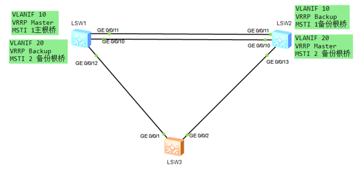
设备连接方式如图所示,网络中存在 VLAN10、20,每个 VLAN 中部署一组 VRRP,使用与
VLAN ID 相同的数值作为 VRID,将 S1 配置为 VLAN10 的 VRRP Master,将 S2 配置为
VLAN20 的 VRRP Master。
同时在 S1、S2、S3 上部署 MSTP,创建 Instance 1、2,将 VLAN10 映射到 MSTI 1、
VLAN20 映射到 MSTI 2,将 S1 配置为 MSTI 1 的主根桥、MSTI 2 的备份根桥,而将 S2 配置
为 MSTI 1 的备份根桥、MSTI 2 的主根桥。
VLANIF 接口地址使用 10.0.x.y/24,其中 x 为 VRID 组号,y 为设备编号,VRIP 使用
10.0.x.254/24。
实验背景:
为了实现网关冗余,作为网络管理员的你在两台汇聚交换机上部署了 VRRP,同时为了实现终
端用户上行数据流量的负载分担,需要在每个 VLAN 中各部署一组 VRRP。为了防止环路,在
交换网络中部署 MSTP,利用 MSTP 的负载分担结合 VRRP 进行协同工作。
实验思路:
1. 所有交换机上创建 VLAN,配置 MSTP,手动指定 S1 为 MSTI 1 的根桥、MSTI 2 的备份
根桥,指定 S2 为 MSTI 1 的备份根桥、MSTI 2 的根桥
2. 在 S1、S2 上创建 VLANIF10、20,部署 VRRP 组 10、20,手动调整 VRRP 优先级,使得
S1 成为 VRRP 组 10 的 Master 设备、S2 成为 VRRP 组 20 的 Master 设备。
3. 部署单跳检测的 BFD,检测 S1、S2 VLANIF 之间连通性,与 VRRP 进行联动,实现
VRRP 的快速切换。
实验步骤
步骤 1 MSTP 基础配置
在所有交换机上创建 VLAN10、20,配置 MSTP 域 hcip,并创建两个新的实例:Instance 1、
Instance 2,将 VLAN10 映射到 Instance 1,将 VLAN20 映射到 Instance 2,同时将 SW1 规
划为 MSTI1 的主根桥、MSTI2 的备份根桥,将 SW2 规划为 MSTI2 的主根桥、MSTI1 的备份
根桥。
#设备命名
略
#关闭本实验中未使用的接口
略
#创建 VLAN
[S1]vlan batch 10 20
[S2]vlan batch 10 20
[S3]vlan batch 10 20
#将所有互联接口配置为 Trunk 接口,放通对应 VLAN
注意一定要放通
#修改 STP 模式为 MSTP
[S1]stp mode mstp
[S2]stp mode mstp
[S3]stp mode mstp
#配置 MSTP
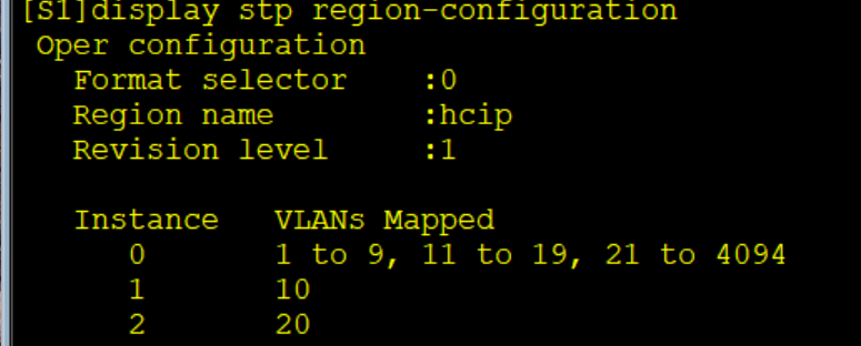
[S1]stp region-configuration
[S1-mst-region] region-name hcip
[S1-mst-region] revision-level 1
[S1-mst-region] instance 1 vlan 10
[S1-mst-region] instance 2 vlan 20
[S1-mst-region] active region-configuration
Info: This operation may take a few seconds. Please wait for a moment...done.
[S1-mst-region] quit
[S2]stp region-configuration
[S2-mst-region] region-name hcip
[S2-mst-region] revision-level 1
[S2-mst-region] instance 1 vlan 10
[S2-mst-region] instance 2 vlan 20
[S2-mst-region] active region-configuration
Info: This operation may take a few seconds. Please wait for a moment...done.
[S2-mst-region] quit
[S3]stp region-configuration
[S3-mst-region] region-name hcip
[S3-mst-region] revision-level 1
[S3-mst-region] instance 1 vlan 10
[S3-mst-region] instance 2 vlan 20
[S3-mst-region] active region-configuration
Info: This operation may take a few seconds. Please wait for a moment...done.
[S3-mst-region] quit
#在 S1 检查 MSTP 实例和 VLAN 的映射关系
#配置 SW1 为 MSTI1 的根桥、MSTI2 的备份根桥
[S1]stp instance 1 root primary
[S1]stp instance 2 root secondary
#配置 SW2 为 MSTI2 的根桥、MSTI1 的备份根桥
[S2]stp instance 1 root secondary
[S2]stp instance 2 root primary
#在 S1 上查看 MSTI1 的状态和统计信息摘要
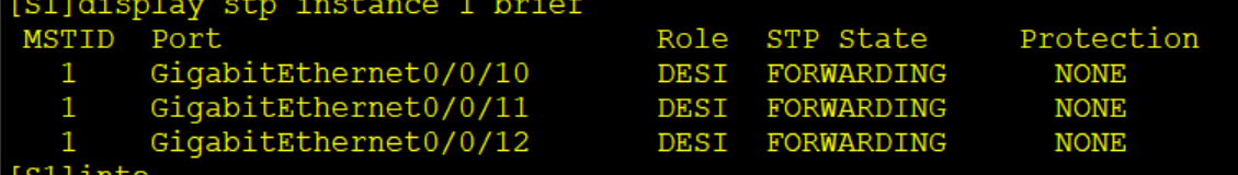
S1 上所有接口都是指定接口,S1 为 MSTI1 的根桥。
#在 S2 上查看 MSTI2 的状态和统计信息摘要
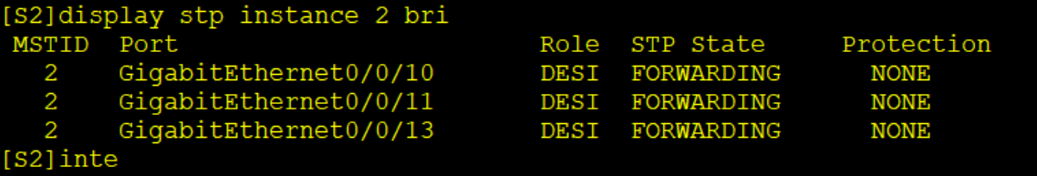
S2 上所有接口都是指定接口,S2 为 MSTI1 的根桥。
步骤 2 VRRP 基础配置
在 S1、S2 均创建 VLANIF 10、20,分别加入 VRRP 组 10、20,手动配置 VRRP 优先级,使
得 S1 的 VLAN10 成为 VRRP Master、S2 的 VLAN20 成为 VRRP Master。
#创建 VLANIF
[S1]interface Vlanif10
[S1-Vlanif10] ip address 10.0.10.1 255.255.255.0
[S1-Vlanif10] quit
[S1]interface Vlanif20
[S1-Vlanif20] ip address 10.0.20.1 255.255.255.0
[S1-Vlanif20] quit
[S2]interface Vlanif10
[S2-Vlanif10] ip address 10.0.10.2 255.255.255.0
[S2-Vlanif10] quit
[S2]interface Vlanif20
[S2-Vlanif20] ip address 10.0.20.2 255.255.255.0
[S2-Vlanif20] quit
#S1 上配置 VRRP
[S1]interface Vlanif 10
[S1-Vlanif10] vrrp vrid 10 virtual-ip 10.0.10.254
[S1-Vlanif10] vrrp vrid 10 priority 120
[S1-Vlanif10] quit
[S1]interface Vlanif 20
[S1-Vlanif20] vrrp vrid 20 virtual-ip 10.0.20.254
[S1-Vlanif20] quit
配置 VLAN10 的 VRRP 优先级为 120,VLAN20 保持默认的 100。
#S2 上配置 VRRP
[S2]interface Vlanif10
[S2-Vlanif10] vrrp vrid 10 virtual-ip 10.0.10.254
[S2-Vlanif10] quit
[S2]interface Vlanif20
[S2-Vlanif20] vrrp vrid 20 virtual-ip 10.0.20.254
[S2-Vlanif20] vrrp vrid 20 priority 120
[S2-Vlanif20] quit
配置 VLAN20 的 VRRP 优先级为 120,VLAN10 保持默认的 100。
#查看 VRRP 组状态
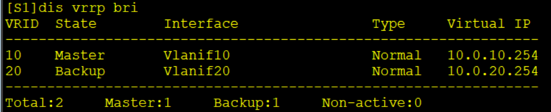
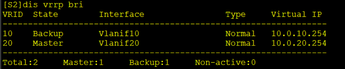
VRRP 组状态与配置预期结果一致。
步骤 3 配置 VRRP 与 BFD 联动进行快速切换
在 S1、S2 上配置 BFD 单跳检测,检测 VLANIF 接口之间的连通性,将 VRRP 与 BFD 联动,
当 BFD 会话状态 Down 时,增加 VRRP Backup 设备的优先级。
#在 S1 上配置 BFD 会话
[S1]bfd
[S1-bfd] quit
[S1]bfd vlanif10 bind peer-ip 10.0.10.2 interface Vlanif10
[S1-bfd-session-vlanif10] discriminator local 1
[S1-bfd-session-vlanif10] discriminator remote 2
[S1-bfd-session-vlanif10] min-tx-interval 100
[S1-bfd-session-vlanif10] min-rx-interval 100
[S1-bfd-session-vlanif10] commit
[S1-bfd-session-vlanif10] quit
[S1]bfd vlanif20 bind peer-ip 10.0.20.2 interface Vlanif20
[S1-bfd-session-vlanif20] discriminator local 11
[S1-bfd-session-vlanif20] discriminator remote 22
[S1-bfd-session-vlanif20] min-tx-interval 100
[S1-bfd-session-vlanif20] min-rx-interval 100
[S1-bfd-session-vlanif20] commit
[S1-bfd-session-vlanif20] quit
#在 S2 上配置 BFD 会话
[S2]bfd
[S2-bfd] quit
[S2]bfd vlanif10 bind peer-ip 10.0.10.1 interface Vlanif10
[S2-bfd-session-vlanif10] discriminator local 2
[S2-bfd-session-vlanif10] discriminator remote 1
[S2-bfd-session-vlanif10] min-tx-interval 100
[S2-bfd-session-vlanif10] min-rx-interval 100
[S2-bfd-session-vlanif10] commit
[S2-bfd-session-vlanif10] quit
[S2]bfd vlanif20 bind peer-ip 10.0.20.1 interface Vlanif20
[S2-bfd-session-vlanif20] discriminator local 22
[S2-bfd-session-vlanif20] discriminator remote 11
[S2-bfd-session-vlanif20] min-tx-interval 100
[S2-bfd-session-vlanif20] min-rx-interval 100
[S2-bfd-session-vlanif20] commit
[S2-bfd-session-vlanif20] quit
#检查 BFD 会话状态
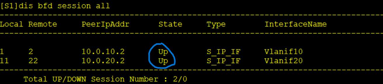
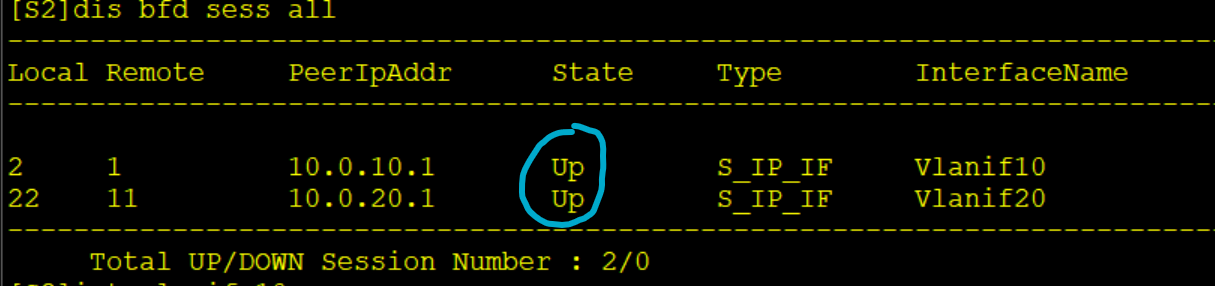
此时 S1、S2 上 BFD 会话状态都为 Up。
#配置 VRRP 与 BFD 联动
[S1]interface Vlanif20
[S1-Vlanif20] vrrp vrid 20 track bfd-session 11 increased 30
[S1-Vlanif20] quit
[S2]interface Vlanif10
[S2-Vlanif10] vrrp vrid 10 track bfd-session 2 increased 30
[S2-Vlanif10] quit
注意,此处的 bfd-session 号为本地的 BFD discriminator,只需要在 Backup 状态的接口上配
置联动,BFD 会话 Down 时增加本地的 VRRP 优先级。
#关闭 S1 上所有接口,模拟链路故障
[S1]interface GigabitEthernet0/0/10
[S1-GigabitEthernet0/0/10] shutdown
[S1-GigabitEthernet0/0/10] quit
[S1]interface GigabitEthernet0/0/11
[S1-GigabitEthernet0/0/11] shutdown
[S1-GigabitEthernet0/0/11] quit
[S1]interface GigabitEthernet0/0/12
[S1-GigabitEthernet0/0/12] shutdown
[S1-GigabitEthernet0/0/12] quit
#在 S2 上查看 BFD 会话状态
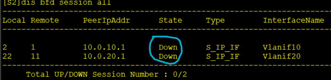
此时两个 BFD 会话状态立马变为 Down。
#在 S2 上查看 VRRP 组状态
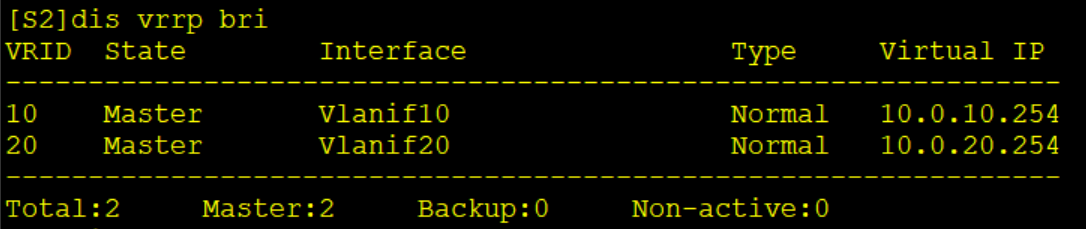
VRRP 组 10、20 的 Master 此时都是 S2
#在 S2 上查看 VRRP 组的状态和配置参数信息
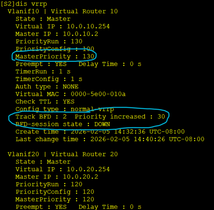
VRRP 组 10 的优先级此时为 130,BFD 会话状态为 Down,BFD 将 VRRP 组 10 的优先级提升
了 30
至此达到了实验目标

DAMO开发者矩阵,由阿里巴巴达摩院和中国互联网协会联合发起,致力于探讨最前沿的技术趋势与应用成果,搭建高质量的交流与分享平台,推动技术创新与产业应用链接,围绕“人工智能与新型计算”构建开放共享的开发者生态。
更多推荐
 11
11 0
0- 0


 已为社区贡献1条内容

所有评论(0)