ESP32 SPI Flash数据模式解析
ESP32 SPI Flash数据模式解析
ESP32 SPI Flash数据模式解析
- 官方文档阅读参考:
- 引导加载程序 (Bootloader):
https://docs.espressif.com/projects/esp-idf/zh_CN/latest/esp32/api-guides/bootloader.htmlhttps://docs.espressif.com/projects/esptool/en/latest/esp32/advanced-topics/spi-flash-modes.html#summary
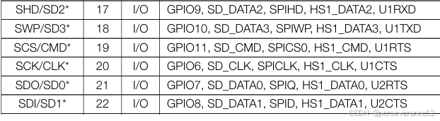
- 外部 Flash与esp32引脚连接
ESP32-WROOM-32 集成了 4 MB 的 SPI flash,连接 ESP32 的管脚 GPIO6,GPIO7,GPIO8,GPIO9,GPIO10和 GPIO11.(即管脚 SCK/CLK,SDO/SD0,SDI/SD1,SHD/SD2,SWP/SD3,和 SCS/CMD)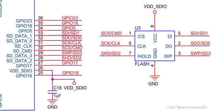
- Strapping 管脚的详细启动模式
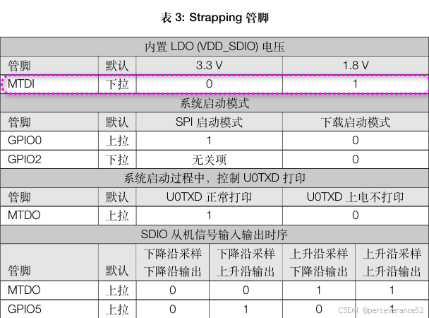
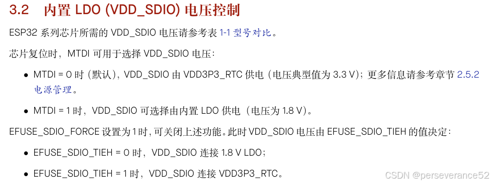
- 在上电复位时,MTDI管脚( GPIO12)的电平状态会影响SPI Flash 供电引脚(VDD_SDIO).电压。可以通过修改熔丝位,跳过检测,后面有介绍。
SPI Flash mode
ESP芯片支持四种不同的SPI闪存访问模式:DIO、DOUT、QIO和QOUT。这些可以通过esptools write-flash的–flash-mode选项进行设置。这些选项控制使用多少I/O引脚与连接的SPI闪存芯片通信,以及使用哪些SPI命令。ESP芯片在从SPI闪存芯片读取或执行代码和数据时使用这些命令。数据被读取,然后在内部缓存到芯片。
- SPI flash access modes: DIO, DOUT, QIO & QOUT速度对照表:
| Option | Mode Name | Pins Used | Speed (ESP device) |
|---|---|---|---|
| qio | Quad I/O | 4 pins used for address & data | Fastest |
| qout | Quad Output | 4 pins used for data | Approx 15% slower than qio |
| dio | Dual I/O | 2 pins used for address & data | Approx 45% slower than qio |
| dout | Dual Output | 2 pins used for data | Approx 50% slower than qio |
- 不同的模式,反应到底层的是对flash读写操作指令的差异:
Dual SPI模式
- 为了提高性能,SPI闪存制造商推出了“双SPI”。在双SPI模式下,MOSI和MISO引脚都用于以每时钟周期两位的速度同时读取或写入数据。与单个SPI相比,某些命令的数据速率提高了一倍。
-
在dout模式下,主机使用“双输出快速读取”(3BH)命令读取数据。每个读取命令和读取地址通过普通SPI从主机发送到闪存芯片,但随后主机通过MOSI和MISO引脚同时读取数据,每个时钟两个位。与仅使用MISO读取数据的单个SPI相比,这使数据搬迁率提高了一倍。
-
在DIO模式下,主机使用“双I/O快速读取”(BBH)命令读取数据。每个读取命令都通过普通SPI从主机发送到闪存芯片,但随后地址通过MOSI和MISO引脚发送到闪存芯片,每时钟两位。之后,主机以与“双输出快速读取”相同的方式每卡读取两位数据。
- 对于ESP芯片,每个命令读取32个字节,音频模式比dout快大约5%。
请参阅特定SPI闪存芯片的数据表,以确定它是否支持这些命令中的一个或两个。
Quad SPI模式
- 为了进一步提高SPI闪存数据传输的性能,SPI闪存制造商引入了“Quad SPI”模式。这种模式增加了两个额外的引脚(否则用于闪存芯片WP和HOLD信号)进行数据传输。这允许双SPI的数据速率翻倍。
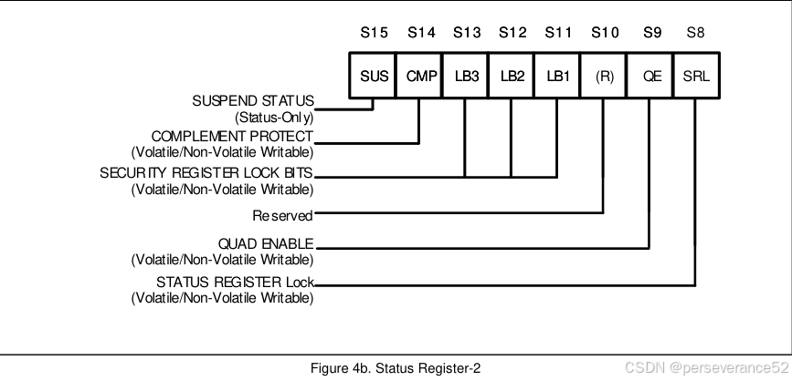
- ✨并非所有闪存芯片都支持Quad SPI模式,也并非所有ESP芯片都将这些引脚连接到SPI闪存芯片。某些闪存芯片需要特殊命令,使能flash 状态寄存器2的QE位,才能启用四线模式。
-
在qout模式下,主机使用“四输出快速读取”(6BH)命令读取数据。该命令与“双输出快速读取”相同,仅在4个引脚上读取数据,而不是每个时钟周期读取4位的2个引脚。这使得数据搬迁的速度正好是“双输出快速读取”的两倍。
-
在qio模式下,主机使用“四I/O快速读取”(EBH)命令读取数据。该命令与“双I/O快速读取”相同,只有地址和数据都在4个引脚上传输,而不是每个时钟周期4位的2个引脚。这使得地址和数据搬迁的速度正好是“双I/O快速读取”的两倍。
是否支持Quad SPI模式的条件
-
SPI闪存芯片的WP和HOLD引脚未连接到乐鑫芯片的正确GPIO。这些引脚必须正确连接才能使四模式工作,并且并非所有板/模块都连接它们。
-
SPI闪存芯片不支持四模式。查找闪存芯片数据表以查看它支持哪些模式。您可以直观地识别闪存芯片,或使用esptools flash-id命令。
-
此芯片型号未正确启用四模式。SPI闪存不是标准,因此每个制造商的芯片实现方式都不同。大多数闪存芯片需要发送某些命令才能启用四SPI模式,这些命令各不相同。对于乐鑫芯片,这通常意味着芯片首先启用Quad SPI模式,然后软件检测芯片类型并尝试启用四SPI模式。如果软件不支持特定的芯片型号,那么它将无法进入四模式。
- 例如GD25QXX的flash芯片,出厂时,状态寄存器2中的QE位默认,值:0,就无法直接使用Quad指令读写操作。
- 通过
esptool --port COM30 read_flash_status命令查询状态寄存器:
esptool --port COM30 read_flash_status --bytes 3
esptool.py v4.8.1
Serial port COM30
Connecting.......
Detecting chip type... Unsupported detection protocol, switching and trying again...
Connecting.....
Detecting chip type... ESP32
Chip is ESP32-D0WDQ6 (revision v1.0)
Features: WiFi, BT, Dual Core, 240MHz, VRef calibration in efuse, Coding Scheme None
Crystal is 40MHz
MAC: 08:3a:f2:8d:cd:e0
Uploading stub...
Running stub...
Stub running...
Status value: 0x0200
Hard resetting via RTS pin...
其中的Status value: 0x0200代表状态寄存器1-2的的值分别:0x00,0x02.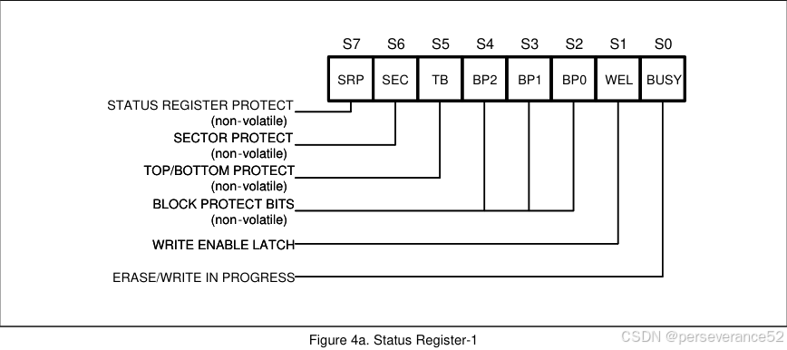
- ESP32仅能查询到2个状态寄存器的值,查询不到3个寄存器的值。但是esp32S3可以。
C:\Users\Administrator>esptool --port COM28 read_flash_status --bytes 3
esptool.py v4.8.1
Serial port COM28
Connecting....
Detecting chip type... ESP32-S3
Chip is ESP32-S3 (QFN56) (revision v0.2)
Features: WiFi, BLE, Embedded PSRAM 8MB (AP_3v3)
Crystal is 40MHz
MAC: 30:30:f9:72:8c:80
Uploading stub...
Running stub...
Stub running...
Status value: 0x400200
Hard resetting via RTS pin...
闪存模式如何与乐鑫芯片通信?
烧录到SPI flash的bootloader. bin文件包含一个标头,其中包含flash速度、flash模式和其他一些元数据。当ROM代码在重置后读取此标头时,初始主机模式由ROM代码确定。将--flash-mode参数传递给esptools将在文件写入flash时更新此标头。
这仅从复位确定用于初始启动的模式。然后,作为启动过程的一部分,软件可以不同地配置闪存模式。
- 例如,在ESP32上,如果ESP-IDF配置为qio/qout模式,那么IDF软件引导加载程序实际上会以dio/dout模式更新。当ROM代码从闪存启动此引导加载程序时,引导加载程序软件会检查闪存芯片型号,并在其余引导过程中启用正确的Quad SPI模式。这是因为在不同的芯片型号上启用Quad SPI有多种不同的方式。
- 对于
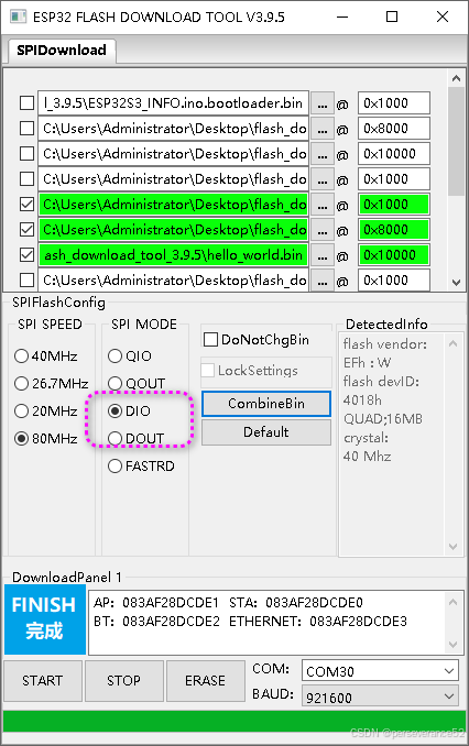
ESP32-D0WDQ6芯片型号,使用esptool刷写程序时,务必将flash模式配置为双线的DIO/DOUT模式.
d:\ESP32\tools\python_env\idf5.4_py3.11_env\Scripts\python.exe d:\ESP32\ESPidf\v5.4\esp-idf\components\esptool_py\esptool\esptool.py -p COM30 -b 460800 --before default_reset --after hard_reset --chip esp32 write_flash --flash_mode dio --flash_freq 80m --flash_size 16MB 0x1000 bootloader/bootloader.bin 0x10000 hello_world.bin 0x8000 partition_table/partition-table.bin
- 对于
ESP32-S3芯片型号,在引导加载程序阶段就可以直接选择四线的qio/qout模式。
📘ESP32 开启QIO/QOUT模式
- 从上面的“闪存模式如何与乐鑫芯片通信”小节内容可知,esp32在通过esptool烧写程序时,esp32引导加载程序实际上是以dio/dout模式更新程序的,当ROM代码从闪存启动此引导加载程序时,引导加载程序软件会检查闪存芯片型号,并在其余引导过程中启用正确的Quad SPI模式.
- 在基于原生espidf开发环境下,在底层组件
bootloader_support中,v5.4\esp-idf\components\bootloader_support\bootloader_flash\src\flash_qio_mode.c包含有使能qio功能函数:void bootloader_enable_qio_mode(void)
esp32基于espidf项目使能qio模式方法
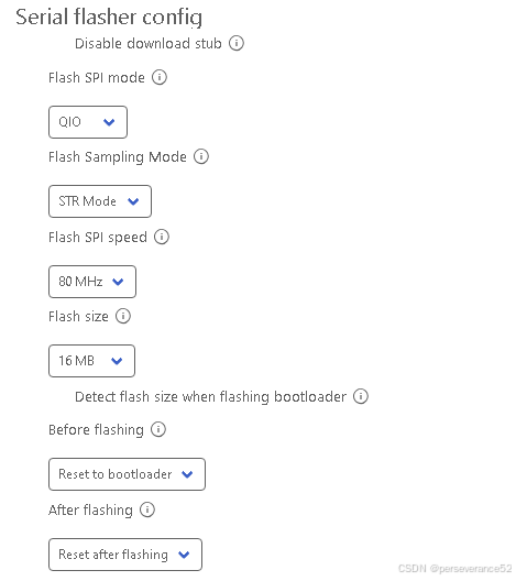
menuconfig配置菜单中,修改flash模式:
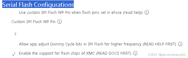
- Serial Flash Configurations:
-
- CMakeLists.txt组件添加组件
idf_component_register(SRCS "hello_world_main.c"
                    PRIV_REQUIRES spi_flash bootloader_support  # 开启qio模式需要bootloader_support组件
                    INCLUDE_DIRS "")
-
- main.c中所需头文件
#include "flash_qio_mode.h"//bootloader_enable_qio_mode
#include "bootloader_flash.h"  //非必须 bootloader_flash_get_spi_mode
void app_main(void)
{
    bootloader_enable_qio_mode();//使能qio
 esp_rom_spiflash_read_mode_t spi_flash_mode =   bootloader_flash_get_spi_mode();//查询spi flash 模式
    while (1)
    {
    printf("Hello world!\n");
    printf("spi_flash_mode: %d\n", spi_flash_mode);
    }

    }
esp_rom_spiflash_read_mode_t枚举类型Mode
typedef enum {
    ESP_ROM_SPIFLASH_QIO_MODE = 0,
    ESP_ROM_SPIFLASH_QOUT_MODE,
    ESP_ROM_SPIFLASH_DIO_MODE,
    ESP_ROM_SPIFLASH_DOUT_MODE,
    ESP_ROM_SPIFLASH_FASTRD_MODE,
    ESP_ROM_SPIFLASH_SLOWRD_MODE,
    ESP_ROM_SPIFLASH_OPI_STR_MODE,
    ESP_ROM_SPIFLASH_OPI_DTR_MODE,
    ESP_ROM_SPIFLASH_OOUT_MODE,
    ESP_ROM_SPIFLASH_OIO_STR_MODE,
    ESP_ROM_SPIFLASH_OIO_DTR_MODE,
    ESP_ROM_SPIFLASH_QPI_MODE,
    ESP_ROM_SPIFLASH_OPI_HEX_DTR_MODE,
} esp_rom_spiflash_read_mode_t;
-
- 串口打印:
[22:45:21.966]收←◆ (181) cpu_start: Pro cpu start user code
I (181) cpu_start: cpu freq: 160000000 Hz
I (181) app_init: Application information:
I (181) app_init: Project name:     hello_world
I (185) app_init: App version:      1
I (188) app_init: Compile time:     Jul  3 2025 20:50:22
I (193) app_init: ELF file SHA256:  43bde6b5f...
I (198) app_init: ESP-IDF:          v5.4-dirty
I (202) efuse_init: Min chip rev:     v0.0
I (206) efuse_init: Max chip rev:     v3.99
I (210) efuse_init: Chip rev:         v1.0
I (214) heap_init: Initializing. RAM available for dynamic allocation:
I (220) heap_init: At 3FFAE6E0 len 00001920 (6 KiB): DRAM
I (225) heap_init: At 3FFB2BD0 len 0002D430 (181 KiB): DRAM
I (230) heap_init: At 3FFE0440 len 00003AE0 (14 KiB): D/IRAM
I (236) heap_init: At 3FFE4350 len 0001BCB0 (111 KiB): D/IRAM
I (241) heap_init: At 4008D110 len 00012EF0 (75 KiB): IRAM
I (247) spi_flash: detected chip: winbond
I (250) spi_flash: flash io: qio
I (254) main_task: Started on CPU0
I (264) main_task: Calling app_main()
I (264) qio_mode: Enabling QIO for flash chip WinBond
Hello world!
spi_flash_mode: 0
This is esp32 chip with 2 CPU core(s), WiFi/BTBLE, silicon revision v1.0, 16MB external flash
Minimum free heap size: 305356 bytes

[22:45:22.947]收←◆Hello world!
spi_flash_mode: 0
esptool 查询flash相关指令
esptool --port COM30 read_flash_status:读flash状态寄存器,默认读取2字节数据。
- 可带参数:
--bytes 1,--bytes 2,--bytes 3
C:\Users\Administrator>esptool --port COM30 read_flash_status
esptool.py v4.8.1
Serial port COM30
Connecting....
Detecting chip type... Unsupported detection protocol, switching and trying again...
Connecting.....
Detecting chip type... ESP32
Chip is ESP32-D0WDQ6 (revision v1.0)
Features: WiFi, BT, Dual Core, 240MHz, VRef calibration in efuse, Coding Scheme None
Crystal is 40MHz
MAC: 08:3a:f2:8d:cd:e0
Uploading stub...
Running stub...
Stub running...
Status value: 0x0200
Hard resetting via RTS pin...
esptool --port COM9 flash_id
C:\Users\Administrator>esptool --port COM30 flash_id
esptool.py v4.8.1
Serial port COM30
Connecting....
Detecting chip type... Unsupported detection protocol, switching and trying again...
Connecting......
Detecting chip type... ESP32
Chip is ESP32-D0WDQ6 (revision v1.0)
Features: WiFi, BT, Dual Core, 240MHz, VRef calibration in efuse, Coding Scheme None
Crystal is 40MHz
MAC: 08:3a:f2:8d:cd:e0
Uploading stub...
Running stub...
Stub running...
Manufacturer: ef
Device: 4018
Detected flash size: 16MB
Flash voltage set by a strapping pin to 3.3V
Hard resetting via RTS pin...
esptool --port COM30 read_flash_sfdp 16 4
C:\Users\Administrator>esptool --port COM30 read_flash_sfdp 16 4
esptool.py v4.8.1
Serial port COM30
Connecting....
Detecting chip type... Unsupported detection protocol, switching and trying again...
Connecting.........
Detecting chip type... ESP32
Chip is ESP32-D0WDQ6 (revision v1.0)
Features: WiFi, BT, Dual Core, 240MHz, VRef calibration in efuse, Coding Scheme None
Crystal is 40MHz
MAC: 08:3a:f2:8d:cd:e0
Uploading stub...
Running stub...
Stub running...
Configuring flash size...
Manufacturer: ef
Device: 4018
Detected flash size: 16MB
SFDP[16..19]: FF FF FF FF
Hard resetting via RTS pin...
esptool --port COM9 write_flash_status --non-volatile --bytes 2 0x0200:写状态寄存器。(Quad SPI模式下,操作不成功)
- 可带参数:
--bytes 1,--bytes 2,--bytes 3
C:\Users\Administrator>esptool --port COM30 write_flash_status --non-volatile --bytes 2 0x0000
esptool.py v4.8.1
Serial port COM30
Connecting......
Detecting chip type... Unsupported detection protocol, switching and trying again...
Connecting....
Detecting chip type... ESP32
Chip is ESP32-D0WDQ6 (revision v1.0)
Features: WiFi, BT, Dual Core, 240MHz, VRef calibration in efuse, Coding Scheme None
WARNING: Detected crystal freq 41.01MHz is quite different to normalized freq 40MHz. Unsupported crystal in use?
Crystal is 40MHz
MAC: 08:3a:f2:8d:cd:e0
Uploading stub...
Running stub...
Stub running...
Initial flash status: 0x0200
Setting flash status: 0x0000
After flash status:   0x0200
Hard resetting via RTS pin...
esptool --port COM30 erase_flash:擦除flash数据espefuse --port COM28 set_flash_voltage 3.3V:设置VDD_SDIO电压为3.3V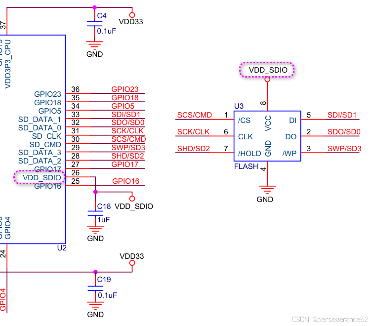
esptool --port COM30 read_flash 0x0 0x20 output.bin:
- 0x0:起始地址(Flash 的 0 地址)。
0x20:读取长度(32 字节)。
output.bin:输出的二进制文件名
C:\Users\Administrator>esptool --port COM30 read_flash 0x0 0x20 output.bin
esptool.py v4.8.1
Serial port COM30
Connecting....
Detecting chip type... Unsupported detection protocol, switching and trying again...
Connecting...........
Detecting chip type... ESP32
Chip is ESP32-D0WDQ6 (revision v1.0)
Features: WiFi, BT, Dual Core, 240MHz, VRef calibration in efuse, Coding Scheme None
Crystal is 40MHz
MAC: 08:3a:f2:8d:cd:e0
Uploading stub...
Running stub...
Stub running...
Configuring flash size...
32 (100 %)
32 (100 %)
Read 32 bytes at 0x00000000 in 0.1 seconds (3.7 kbit/s)...
Hard resetting via RTS pin...
espefuse --port COM30 summary:获取详细信息
C:\Users\Administrator>espefuse --port COM30 summary
espefuse.py v4.8.1
Connecting......
Detecting chip type... Unsupported detection protocol, switching and trying again...
Connecting....
Detecting chip type... ESP32

=== Run "summary" command ===
EFUSE_NAME (Block) Description  = [Meaningful Value] [Readable/Writeable] (Hex Value)
----------------------------------------------------------------------------------------
Calibration fuses:
ADC_VREF (BLOCK0)                                  True ADC reference voltage                         = 1093 R/W (0b10001)

Config fuses:
WR_DIS (BLOCK0)                                    Efuse write disable mask                           = 0 R/W (0x0000)
RD_DIS (BLOCK0)                                    Disable reading from BlOCK1-3                      = 0 R/W (0x0)
DISABLE_APP_CPU (BLOCK0)                           Disables APP CPU                                   = False R/W (0b0)
DISABLE_BT (BLOCK0)                                Disables Bluetooth                                 = False R/W (0b0)
DIS_CACHE (BLOCK0)                                 Disables cache                                     = False R/W (0b0)
CHIP_CPU_FREQ_LOW (BLOCK0)                         If set alongside EFUSE_RD_CHIP_CPU_FREQ_RATED; the = False R/W (0b0)
                                                    ESP32's max CPU frequency is rated for 160MHz. 24
                                                   0MHz otherwise
CHIP_CPU_FREQ_RATED (BLOCK0)                       If set; the ESP32's maximum CPU frequency has been = True R/W (0b1)
                                                    rated
BLK3_PART_RESERVE (BLOCK0)                         BLOCK3 partially served for ADC calibration data   = False R/W (0b0)
CLK8M_FREQ (BLOCK0)                                8MHz clock freq override                           = 55 R/W (0x37)
VOL_LEVEL_HP_INV (BLOCK0)                          This field stores the voltage level for CPU to run = 0 R/W (0b00)
                                                    at 240 MHz; or for flash/PSRAM to run at 80 MHz.0
                                                   x0: level 7; 0x1: level 6; 0x2: level 5; 0x3: leve
                                                   l 4. (RO)
CODING_SCHEME (BLOCK0)                             Efuse variable block length scheme
   = NONE (BLK1-3 len=256 bits) R/W (0b00)
CONSOLE_DEBUG_DISABLE (BLOCK0)                     Disable ROM BASIC interpreter fallback             = True R/W (0b1)
DISABLE_SDIO_HOST (BLOCK0)                                                                            = False R/W (0b0)
DISABLE_DL_CACHE (BLOCK0)                          Disable flash cache in UART bootloader             = False R/W (0b0)

Flash fuses:
FLASH_CRYPT_CNT (BLOCK0)                           Flash encryption is enabled if this field has an o = 0 R/W (0b0000000)
                                                   dd number of bits set
FLASH_CRYPT_CONFIG (BLOCK0)                        Flash encryption config (key tweak bits)           = 0 R/W (0x0)

Identity fuses:
CHIP_PACKAGE_4BIT (BLOCK0)                         Chip package identifier #4bit                      = False R/W (0b0)
CHIP_PACKAGE (BLOCK0)                              Chip package identifier                            = 0 R/W (0b000)
CHIP_VER_REV1 (BLOCK0)                             bit is set to 1 for rev1 silicon                   = True R/W (0b1)
CHIP_VER_REV2 (BLOCK0)                                                                                = False R/W (0b0)
WAFER_VERSION_MINOR (BLOCK0)                                                                          = 0 R/W (0b00)
WAFER_VERSION_MAJOR (BLOCK0)                       calc WAFER VERSION MAJOR from CHIP_VER_REV1 and CH = 1 R/W (0b001)
                                                   IP_VER_REV2 and apb_ctl_date (read only)
PKG_VERSION (BLOCK0)                               calc Chip package = CHIP_PACKAGE_4BIT << 3 + CHIP_ = 0 R/W (0x0)
                                                   PACKAGE (read only)

Jtag fuses:
JTAG_DISABLE (BLOCK0)                              Disable JTAG                                       = False R/W (0b0)

Mac fuses:
MAC (BLOCK0)                                       MAC address
   = 08:3a:f2:8d:cd:e0 (CRC 0x48 OK) R/W
MAC_CRC (BLOCK0)                                   CRC8 for MAC address                               = 72 R/W (0x48)
MAC_VERSION (BLOCK3)                               Version of the MAC field                           = 0 R/W (0x00)

Security fuses:
UART_DOWNLOAD_DIS (BLOCK0)                         Disable UART download mode. Valid for ESP32 V3 and = False R/W (0b0)
                                                    newer; only
ABS_DONE_0 (BLOCK0)                                Secure boot V1 is enabled for bootloader image     = False R/W (0b0)
ABS_DONE_1 (BLOCK0)                                Secure boot V2 is enabled for bootloader image     = False R/W (0b0)
DISABLE_DL_ENCRYPT (BLOCK0)                        Disable flash encryption in UART bootloader        = False R/W (0b0)
DISABLE_DL_DECRYPT (BLOCK0)                        Disable flash decryption in UART bootloader        = False R/W (0b0)
KEY_STATUS (BLOCK0)                                Usage of efuse block 3 (reserved)                  = False R/W (0b0)
SECURE_VERSION (BLOCK3)                            Secure version for anti-rollback                   = 0 R/W (0x00000000)
BLOCK1 (BLOCK1)                                    Flash encryption key
   = 00 00 00 00 00 00 00 00 00 00 00 00 00 00 00 00 00 00 00 00 00 00 00 00 00 00 00 00 00 00 00 00 R/W
BLOCK2 (BLOCK2)                                    Security boot key
   = 00 00 00 00 00 00 00 00 00 00 00 00 00 00 00 00 00 00 00 00 00 00 00 00 00 00 00 00 00 00 00 00 R/W
BLOCK3 (BLOCK3)                                    Variable Block 3
   = 00 00 00 00 00 00 00 00 00 00 00 00 00 00 00 00 00 00 00 00 00 00 00 00 00 00 00 00 00 00 00 00 R/W

Spi Pad fuses:
SPI_PAD_CONFIG_HD (BLOCK0)                         read for SPI_pad_config_hd                         = 0 R/W (0b00000)
SPI_PAD_CONFIG_CLK (BLOCK0)                        Override SD_CLK pad (GPIO6/SPICLK)                 = 0 R/W (0b00000)
SPI_PAD_CONFIG_Q (BLOCK0)                          Override SD_DATA_0 pad (GPIO7/SPIQ)                = 0 R/W (0b00000)
SPI_PAD_CONFIG_D (BLOCK0)                          Override SD_DATA_1 pad (GPIO8/SPID)                = 0 R/W (0b00000)
SPI_PAD_CONFIG_CS0 (BLOCK0)                        Override SD_CMD pad (GPIO11/SPICS0)                = 0 R/W (0b00000)

Vdd fuses:
XPD_SDIO_REG (BLOCK0)                              read for XPD_SDIO_REG                              = False R/W (0b0)
XPD_SDIO_TIEH (BLOCK0)                             If XPD_SDIO_FORCE & XPD_SDIO_REG                   = 1.8V R/W (0b0)
XPD_SDIO_FORCE (BLOCK0)                            Ignore MTDI pin (GPIO12) for VDD_SDIO on reset     = False R/W (0b0)

Flash voltage (VDD_SDIO) determined by GPIO12 on reset (High for 1.8V, Low/NC for 3.3V)
- 其中
Flash voltage (VDD_SDIO) determined by GPIO12 on reset (High for 1.8V, Low/NC for 3.3V):ESP32 的 VDD_SDIO(Flash 供电电压) 是由 GPIO12(MTDI 引脚)在复位时的电平状态决定的。
XPD_SDIO_REG = False (0b0)
表示 VDD_SDIO 不由内部 LDO 调节器控制,而是由 GPIO12 的硬件状态决定。
XPD_SDIO_FORCE = False (0b0)
表示 需要检测 GPIO12 引脚的电平(不忽略 GPIO12 的功能)。
XPD_SDIO_TIEH = 0b0
这个值在 XPD_SDIO_FORCE=False 时无效,实际电压由 GPIO12 决定。
- 在esp32上电复位时,需要确保GPIO12(MTDI 引脚),低电平或悬空(NC),让VDD_SDIO 电压为3.3V.
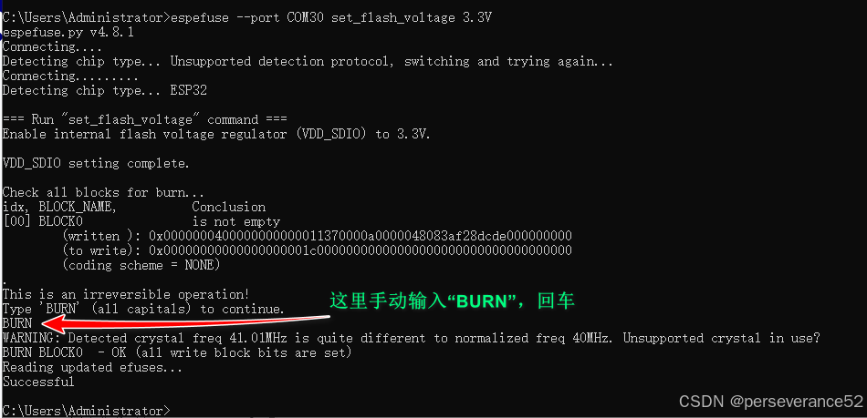
espefuse --port COM30 set_flash_voltage 3.3V:强制设置 VDD_SDIO 电压并忽略 GPIO12.(设置 XPD_SDIO_FORCE=1(忽略 GPIO12))
C:\Users\Administrator>espefuse --port COM30 set_flash_voltage 3.3V
espefuse.py v4.8.1
Connecting....
Detecting chip type... Unsupported detection protocol, switching and trying again...
Connecting.........
Detecting chip type... ESP32

=== Run "set_flash_voltage" command ===
Enable internal flash voltage regulator (VDD_SDIO) to 3.3V.

VDD_SDIO setting complete.

Check all blocks for burn...
idx, BLOCK_NAME,          Conclusion
[00] BLOCK0               is not empty
        (written ): 0x0000000400000000000011370000a0000048083af28dcde000000000
        (to write): 0x00000000000000000001c00000000000000000000000000000000000
        (coding scheme = NONE)
.
This is an irreversible operation!
Type 'BURN' (all capitals) to continue.
- 该命令属于一次性配置,输入
BURN回车确认后,就生效了。后续esp32复位重启,不再受GPIO12(MTDI 引脚)影响。

DAMO开发者矩阵,由阿里巴巴达摩院和中国互联网协会联合发起,致力于探讨最前沿的技术趋势与应用成果,搭建高质量的交流与分享平台,推动技术创新与产业应用链接,围绕“人工智能与新型计算”构建开放共享的开发者生态。
更多推荐


 7
7 0
0- 0


 已为社区贡献18条内容

所有评论(0)